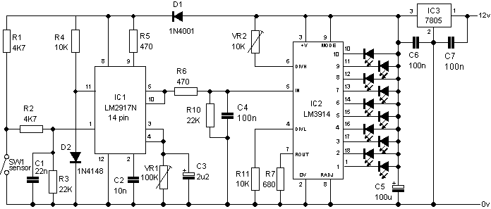
An easy way of measuring RPM is to convert the frequency of a sensor attached to the motor into a proportional voltage. The LM2917N Frequency to Voltage Converter is designed exactly for that job. The IC comes in 2 versions, 8 pin (LM2917N-8) and 14 pin (LM2917N) versions. Both have a voltage regulator built in, so if no other chips are required, you don't need a 7805.
The minimal circuit shown first on this page gives an output of about 1 volt per 66Hz input. The input must be AC and not a pulsed DC input. This circuit is based on the 8 pin version.
Vout=Vcc x Fin x R1 x C2: where Fin=input frequency in hertz, R1=resistance connected to pin 3 ,C2=capacitance connected to pin 2, and Vcc is not 12, but instead 7.5 volts (from the on-board regulator).

In the more practical circuit shown next, the input is conditioned by R1 - R3 and C1 to convert a simple switch closure (such as the points in an automotive ignition) into an AC signal suitable for the 2917. The output is smoothed by R6/C4 and fed into a LM3914 based bar graph display driver. Two pots adjust the scale and range of the display. This circuit is based on the 14 pin version.

Note: RPM=(120 x freq.)/ (# of cylinders) and freq = ((# of cylinders)*(RPM))/120
A component placment diagram and PCB layout are available in pcb.pdf
