Documentation
Source Code:
1 - Create a generic modular hardware interface and associated driver routines that can be easily used in other more complex projects. I wanted the complexity to be non-trivial, but not overwhelming, either.
2 - Learn how to program an AVR using the GNU AVR-GCC compiler tool chain.
3 - Develop a useful, but simple macro set that can easily be reusable. This completely eliminates low level assembler-like AVR uC extension instructions in the high level C++ application code. The macro names are intended to be self-documenting. This, in turn, eliminates the need for line-by-line instruction documentation which greatly speeds up application development.
4 - Develop good debugging methods without resorting to using a software based debugger.
I chose to use a discontinued LCD module, the Phico 'M-0 9949 94V-0", because it has 3 LEDS, 4 pushbutton switches and a contrast control pot built into it. It's an old model which uses the +5 volt-only Hitachi HD44780 LCD display controller. This unit happens to have a 2-line by 40 character memory and a 2 by 16 character physical display. This particular module model does not have an LED backlight. Most LCD character modules on the market do have a backlight.
The driver can be used with any 1, 2 or 4 line Hitachi-HD44780-controled LCD display module. I implemented only the 4-bit data bus mode because there few or no reasons to use the full 8-bit data bus. Actually, I first wrote the code for only the 8-bit data mode to make debugging the timing signals easier, but later removed that option.
Since all the code is written in C++ there should not be too much of an effort needed to convert the code for use with a different compiler or even another uC family (PIC ?). I separated the code into separate files because I use different combinations of those utility functions in other projects. I like to be able to "mix and match" at will.
I have also included lots of peripheral documentation. Complete code documentation is located within their individual files.
1 - The data sheet for the Hitachi HD44780(U) really sucks, even despite it being updated for inclusion of the 'U' lower voltage part variation. All the glaring omissions present in the original version were carried over unchanged into the updated version. This has nothing to do with Japanese-to-English translation problems. Their technical writers were simply very sloppy.
2 - Since I didn't (want to learn and) use a software debugger, I designed and hand-built small, but very useful pieces of prototyping and debugging hardware that includes an 8-bit high impedance LED display module and a ribbon-cable-to-solderless-breadboard adapter. I am surprised they turned out so well.
3 - How to get the GNU AVR-GCC compiler tool chain to "sing and dance" any way I want it to using it on the Windows XP platform. I would have probably chosen to use the WinAVR IDE if I hadn't already learned to use the native GNU C++ tool chain for Windows PCs. I will use WinAVR for larger projects, but for this one it seemed like overkill.
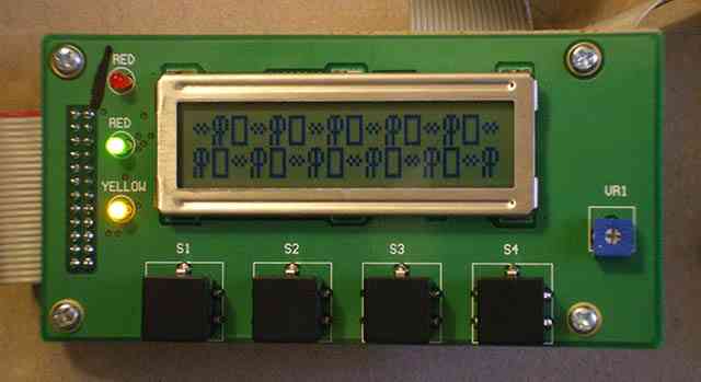
The module shown "in action". From this photo you can't tell that the LEDs are counting in binary and that the display window is shifting leftward by 3 characters per second. Note the natural high contrast - that's why this module needs no backlight. The manufacturer of the basic LCD module mounted to the PCB is unknown, which is typical.
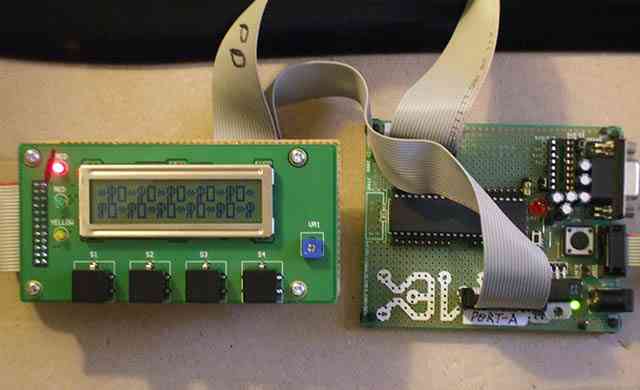
It just doesn't get much simpler than this! Just barely visible is my adapter board mounted to the back of the LCD module. It has just the 3 shrouded ribbon cable PCB connectors and a bunch of 30 AWG wire-wrap wires soldered to the appropriate pins. 20-pin ribbon cable shrouded PCB headers are perfect for mounting on the Olimex AVR-P40-8535 board. So far just the A and D ports are wired up, but there's lust room enough for the B and C ports, too.
I added the ribbon cable headers and single row pin headers for use as convenient test points. I also added the green T1 LED (and its current limiting resistor) to this Olimex board. It serves simply as a power-on indicator, which is glaringly lacking in the Olimex design. An ATMega16-PU is being used here.
The programmer used (not shown) is the LadyAda USBtinyISP which also serves to power the system with up to 100 mA of +5V. The USBtinyISP is implemented with an Atmel ATiny uC ! AVRDude is used to download and verify the code programming into FLASH and EEROM.
Please send questions, comments, suggestions, etc., to:
greenpieces77(at)yahoo.com
// LCDPAR.C        - For 4-bit Parallel xfaces

/*
    No rights reserved by Ray Pasco, 2009-11-16
    Use, modify and distribute as you wish. There is no warranty of any kind.
    This is a "beerware" license.
*/

// AVR definitions
#include <avr\io.h>
#include <stdint.h>         // byte
#include <util\delay.h>     // _delay_ms(), _delay_us()
#include <string.h>

// My own mult-project definitions and utilities
#include "Delay.h"          // Delay_ms(), Delay_us()
#include "BitManip.h"       // BitsX()
#include "DataManip.c"      // Byte_2_Hex()

// -----------

// Project-specific routines and definitions
#include "LCD_RDP.c"

//====================================================

// Global configuration variables. These will save the configuration state
//   first set in Lcd_Init() for later modification.
// Using this variable value, only the config bits that need to be changed can be altered
//   by calling Lcd_Command(). This value also contains the configuration op code.

//static byte LdcDisplayCfgCmd ;

//----------------------------------------------------

void    Lcd_Print_Hex2( byte abyte )     // Display address/position must already be set.
{
    word  hex2 ;

    hex2 = Byte_2_Hex( abyte ) ;
    Lcd_Print_Char( hex2 >> 8 ) ;        // display the upper hex char
    Lcd_Print_Char( hex2 & 0x00FF ) ;    // display the lower hex char
}

//----------------------------------------------------

void   Lcd_Fill_Lines( void )   // write a char pattern to fill every display line
{
    byte iStart=200, i, j, ledCtr=0 ;


    // Write the display chars only once.
    Lcd_Command( LCD_SET_DDRAM_ADDR | LCD_ADDR_LINE1 ) ;    // start of 1st line

    for (i=iStart; i<iStart+(LCD_CHARS_PER_LINE >> 2); i++)
    {
        j = i + i ;
        Lcd_Print_Hex2( (char) j ) ;
        Lcd_Print_Str( "  " ) ;
    }

    if (LCD_NUM_LINES == 2)
    {
        Lcd_Command( LCD_SET_DDRAM_ADDR | LCD_ADDR_LINE2 ) ;    // start of 1st line
        for (i=iStart; i<iStart+(LCD_CHARS_PER_LINE >> 2); i++)
        {
            Lcd_Print_Str( "  " ) ;
            j = i + i + 1;
            Lcd_Print_Hex2( (char) j ) ;
        }
    }
}

//----------------------------------------------------

void    Lcd_Scroll_And_Blink( void )    // Sample application. Loop forever.
{
    byte iStart=200, i=0, j ;


    Lcd_Init() ;
    Lcd_Clear() ;
    Delay_us( 2000 ) ;

    // Write the display chars only once.
    Lcd_Fill_Lines() ;

    for(;; i++)
    {
        Lcd_Command( LdcDisplayCfgCmd |= LCD_DISPLAY_ON ) ;
        Delay_ms( 300 ) ;   // any shorter delay makes the display difficult to read

        if ( ((i >> 2) << 2 ) == i )    // Modulo-4
            Lcd_Command( LdcDisplayCfgCmd &= ~LCD_DISPLAY_ON ) ;

        Lcd_Display_Shift_Window_Right( 1 ) ;

        if ((i & 0x07) != 0)    // 3 out of 4 iterations (when != 0)
        {
            // Make the LEDs will flash in the binary up-counting fashion.
            BitsSet( LCD_LED_PORT, ( (i & 0x07) << 3 ) ) ;  // shift 'i''s binary value into the LEDs' pin positions.
            Delay_ms( 125 ) ;                               // only a short LED 'on' flash
            BitsClr( LCD_LED_PORT, LCD_LED_ALL ) ;          // all LEDs off again
        }
    }
}

//====================================================

void    Lcd_Define_Custom_Chars( void )
{

    const byte custChar0[ 8 ] = {0x0E, 0x15, 0x15, 0x15,
                                 0x0E, 0x14, 0x14, 0x14 } ;
    Lcd_Custom_Char_Define( 0, custChar0 ) ;

    const byte custChar1[ 8 ] = {0xFF, 0x11, 0x11, 0x11,
                                 0x11, 0x11, 0x11, 0xFF } ;
    Lcd_Custom_Char_Define( 1, custChar1 ) ;

    const byte custChar2[ 8 ] = {0x00, 0x00, 0x0A, 0x15,
                                 0x0A, 0x00, 0x00, 0x00 } ;
    Lcd_Custom_Char_Define( 2, custChar2 ) ;

}

//====================================================

void    Lcd_Display_Custom_Chars( void )
{
    byte i, j, k[2]={LCD_ADDR_LINE1, LCD_ADDR_LINE2} ;


    Lcd_Init() ;
    Delay_ms( 1000 ) ;      // Light up all the LEds and the init message.

    Lcd_Clear() ;
    Lcd_Define_Custom_Chars() ;

    Lcd_Command( LCD_SET_DDRAM_ADDR | LCD_ADDR_LINE1 ) ;  // start of line
    SIMPLE_LOOP( i, 40 )
    {
        Lcd_Print_Custom_Char( i % 3 ) ;        // modulo to range [0..2]
    }

    Lcd_Command( LCD_SET_DDRAM_ADDR | LCD_ADDR_LINE2 ) ;
    SIMPLE_LOOP( i, 40 )
        Lcd_Print_Custom_Char( (i+1) % 3 ) ;        // modulo to range [0..2]

    Delay_ms( 1000 );

    for (;;)        // forever
    {
        Lcd_Display_Shift_Window_Left( 1 ) ;
        i += 1 ;
        BitsClr( LCD_LED_PORT,  LCD_LED_ALL ) ;     // turn off all LEDs
        BitsSet( LCD_LED_PORT, ((i % 8) << 3) ) ;   // binary counting with LEDs

        Delay_ms( 500 );
    }
}

//=============================================================================

int    main( void )
{

    //Lcd_Scroll_And_Blink() ;        // Sample app good for checking basic functionality.

    Lcd_Display_Custom_Chars() ;  // Sample app good for checking basic functionality.

    //---------------

    for (;;)
    {
    }
}
// LCD.H

/*
    No rights reserved by Ray Pasco, 2009-11-16
    Use, modify and distribute as you wish. There is no warranty of any kind.
    This is a "beerware" license.
*/

// Definitions so that main() will *never* have to know about ports, pins or bits.
// After all, what would be the point of writing high level C code ?!

#ifndef __LCD_H__
#define __LCD_H__


// AVR definitions
#include <avr\io.h>
#include <stdint.h>         // uint8_t

#include "BitManip.h"

// ---------------------------------------------------------

static byte LdcDisplayCfgCmd ;

// ---------------------------------------------------------

/*
  My particular LCD module is a discontinued custom Phico model [ M-0 9949 94V-0 ]
  available only thru Massmind.org (until they are sold out). It has an ordinary
  HC44780 +5V (only) controller. The module also has 4 non-standard LEDs and 4 NO
  pushbutton switches. Both the LEDs and the switches are hard-wired to ground.

  To a ccomodate the 3 LED drives and 4 switch sense lines the module has a non-standard
  24-pin dual row connector with 0.1 inch pin spacing (not the common 16-pin connectior)
  The 3# LEDs have no current-limiting resistors which must be supplied off-board.
  The 4# NO pushubuttons also need off-board pull-up resistors to operate.
  The module has a convenient 10K pot for manual contrast adjustment. A negative
  contrast-adjust voltage is neede *only* if the ambient temperature falls below 0 degrees F.
*/

#define LCD_NUM_LINES       2       // 1, 2 or 4 lines are avaiable.
#define LCD_CHARS_PER_LINE  40      // Think of the display as a window into the full line.
#define LCD_WINDOW_SIZE     16      // 16 or 20 are commonly avaiable
#define LCD_CHAR_SIZE       8       // 8 or 10 raster character display modes are implemented by the '77480

/*

################  IMPORTANT DESIGN RULES  #################

There are 4 groups of pins:  3# control outputs, the 4-bit data bus,
3# LEDs drive outputs and 2# (out of 4# available) push-button switch inputs.

Each group of signals may be assigned to any *ONE, AND ONLY ONE* port.
I.e., do *not* split any of each group's pins among multiple ports.

Each group may be assigned to any port. Multiple groups may be asigned to the same port.

The pin assignments within any group need NOT be contiguous or in any particular order.

These design rules allow an optimum balance of coding simplicity/efficiency with pin assignment flexibility.

*/

// -----------

// Modify the port letter and the pin numbers as desired for the particular hardware implementation.

#define LCD_CTRL_PORT   PORTD   // set to any one port
#define LCD_CTRL_DIR    DDRD    // control signals need only to be write-only

// Control signal pin allocations. Change as necessary.
// Port bit assignments.  Values to be used with BitsSet() and BitsClr() macros.
// The particular pin number assignments may be completely arbitrary if needed.
#define LCD_RS          0x01    // this indicates the bit position for the port's d0 pin
#define LCD_RW          0x02    // d1
#define LCD_EN          0x04    // d2

#define LCD_CTRL_ALL   ( LCD_RW | LCD_EN | LCD_RS )

// -----------

// Port-A[7..0] <==> LCD D[7..0]   bidirectional data bus. When using inputs, use no internal pull-ups.

// Modify the port letter and the pin numbers as desired for your particular hardware interface implementation.

#define LCD_DATA_PORT       PORTA   // Set all to any convenient port
#define LCD_DATA_DIR        DDRA    // Bi-directional when reading the Busy Flag status bit. RAM reading does not work !
#define LCD_DATA_PIN        PINA    // For reading purposes.

#   define LCD_DATA_D7      0x80    // This bit has extra functionality as the Busy Flag.
#   define LCD_DATA_D6      0x40
#   define LCD_DATA_D5      0x20
#   define LCD_DATA_D4      0x10

#   define LCD_DATA_ALL     ( LCD_DATA_D7 | LCD_DATA_D6 | LCD_DATA_D5 | LCD_DATA_D4 )
#   define LCD_BUSY_FLAG    0x80    // Is d7, also.

// -----------

// This particular Phico module has had its middle red LED replaced by me with a green one.
// I don't want a duplicate red LED when there are other colors available.
// #########  Don't drive the LEDs without current-limiting resistors installed  #########

// Modify the port letter and the pin numbers as desired for your particular hardware implementation.

#define LCD_LED_PORT    PORTD   // set to any single port
#define LCD_LED_DIR     DDRD    // write-only pins

#define LCD_LED_YEL     0x20
#define LCD_LED_GRN     0x10
#define LCD_LED_RED     0x08

#define LCD_LED_ALL    ( LCD_LED_RED | LCD_LED_GRN | LCD_LED_YEL )

// -----------

// Modify the port letter and the pin numbers as desired for your particular hardware implementation.

// SW3 and SW4 are not connected.  All switches need internal input pin pull-ups to operate properly.

#define LCD_SW_PORT     PORTD   // set to any single port
#define LCD_SW_DDR      DDRD    // read-only pins
#define LCD_SW_PIN      PIND

#define LCD_SW1         0x40
#define LCD_SW2         0x80    // No more pins available on the control port for SW2 and SW3

#define LCD_SW_ALL      ( LCD_SW1 | LCD_SW2 )

// --------------------------------------------------------------------------------------

// LCD Op Control definitions

// RS=1 == RAM op       RW*=1 == READ op
// RS=0 == REG op       RW*=0 == WRITE op
#define LCD_RAM_OP          BitsSet( LCD_CTRL_PORT, LCD_RS )
#define LCD_REG_OP          BitsClr( LCD_CTRL_PORT, LCD_RS )

#define LCD_READ_OP         BitsSet( LCD_CTRL_PORT, LCD_RW )
#define LCD_WRITE_OP        BitsClr( LCD_CTRL_PORT, LCD_RW )

#define LCD_EN_SET          BitsSet( LCD_CTRL_PORT, LCD_EN ) ; LCD_EN_DELAY
#define LCD_EN_CLR          BitsClr( LCD_CTRL_PORT, LCD_EN )

#define LCD_RAM_WRITE_OP    LCD_RAM_OP ; LCD_WRITE_OP
#define LCD_REG_WRITE_OP    LCD_REG_OP ; LCD_WRITE_OP

// Hitachi HC44780(U) command definitions made for convenience and code readability purposes.
// The following 2 ops are special "aggregate op" functions. Their execution completions can only be timed.
// This means, other than taking a relatively very long time to execute, the Busy Flag is not valid.
// Op completion can be assured only by using a timer. This driver uses a software timer for simplicity.

#define LCD_CLEAR_DISPLAY_OP    0x01    // ~1750 usec to complete. The Busy Flag *can not* be used for this op.

#define LCD_RETURN_HOME_OP      0x02    // ~1750 usec to complete. The Busy Flag *can not* be used for this op.

// "Normal" (non-aggregate) ops taking about 50 uSec each to complete. The Busy Flag is available
// to test for command op completion status. The driver could have easily used timing instead.

// Bit-wise "OR" all the option bits with their associated op command code.

#define LCD_ENTRY_MODE_OP       0x04        // cursor movement direction with optional display shift
// b1 = I/D: 1=increment, 0=decrement. C    ursor automatically moves with data reads & writes.
// b0 = S:   1=accompanying display shift, 0=no accompanying display shift
#define LCD_ENTRY_MODE_INC  0x02    //       move the cursor position/DDRAM address 1 char to the right when writing a char
#define LCD_ENTRY_MODE_DEC  0x00    // don't move the cursor position/DDRAM address 1 char to the right when writing a char
//
#define LCD_ENTRY_MODE_SHIFT    0x01        // do    shift the display window when writing a character
#define LCD_ENTRY_MODE_NO_SHIFT 0x00        // don't shift the display window when writing a character


#define LCD_DISPLAY_OP      0x08
//
#define LCD_DISPLAY_ON      0x04    // The power-up default shows the written characters within the display window
#define LCD_DISPLAY_OFF     0x00    // This blanks the display, but does not change the DDRAM's or CGRAM's contents
//
#define LCD_DISPLAY_CURSOR_UNDERSCORE_ON  0x02    // do    show an underscore at the current cursor position
#define LCD_DISPLAY_CURSOR_UNDERSCORE_OFF 0x00    // don't show an underscore at the current cursor position
//
// The blinking block character is shown independently of the cursor, but is at the cursor position.
#define LCD_DISPLAY_CHAR_BLINK_ON       0x01    // don't blink the char at the cursor position
#define LCD_DISPLAY_CHAR_BLINK_OFF      0x00    // do    blink the char at the cursor position


#define LCD_SHIFT_OP        0x10    // shift cursor or display (without DDRAM change)
// The current CG/DDRAM address is always incremented when writing display or character graphics data.
// Enabling the display window to move does not change this even though the apparent (shown) cursor position
//   does not appear to shift relative to the physical display.
#define LCD_SHIFT_DISPLAY   0x08    // shift the display window rather than the apparent cursor postion when writing
#define LCD_SHIFT_CURSOR    0x00    // keep the display window stationary and move the cursor position when writing
//
#define LCD_SHIFT_RIGHT     0x04    // shift the display window to the right when writing display data.
#define LCD_SHIFT_LEFT      0x00    // shift the display window to the left  when writing display data.


#define LCD_FUNCTION_OP     0x20    // pysical data bus width, physical number of display lines, displayed font size
//
#define LCD_FUNCTION_8BIT   0x10    // the physical xface uses all 8 data bus lines
#define LCD_FUNCTION_4BIT   0x00    // the physical xface uses only 4 data bus lines
//
#define LCD_FUNCTION_2LINE  0x08    // the physical display has 2 text lines.
#define LCD_FUNCTION_1LINE  0x00    // the power-up default. The display has 1 physical text line.
// b2=font select: 1=5x10, 0=5x8
#define LCD_FUNCTION_5X10   0x04    // ? What does this mode do ?!
#define LCD_FUNCTION_5X8    0x00    // This option works as expected.


#define LCD_SET_CGRAM_ADDR  0x40    // CGRAM writing start addr. The next CGRAM write op will be to here.
// b5..b0: CGRAM start address      // The address can be auto-incremented on each CGRAM data access.

#define LCD_SET_DDRAM_ADDR  0x80    // DDRAM address (the displayed character position) that will be used
                                    // on next character code write op. Also can be auto-incremented on every access.
//
#define LCD_ADDR_LINE1      0x00    // convenience def for the DDRAM address of the 1st line's beginning char position
#define LCD_ADDR_LINE2      0x40    // convenience def for the DDRAM address of the 2nd line's beginning char position

// Add the start addresses for the beginning of 3 and 4-line displays. Their addresses are not at all intuitive !

// ---------------------------------------------------------

// Convenience defs for some of the most useful built-in HC44780(U) characters.
//
#define ALPHA       0xE0
#define BETA        0xE2
#define INFINITY    0xF3
#define MU          0xE4
#define OHM         0xF4
#define RHO         0xE6
#define SIGMA       0xF6
#define PI          0xF7
#define FOOTNOTE1   0xEB    // math complex conjugate symbol as well ?
#define FOOTNOTE2   0xB7
#define MEAN        0xF8    // mathematical mean (x_bar)
#define DEGREE      0xDF
#define THEREEXISTS 0xAE
#define BLOCK       0xFF    // a filled vertical rectangle

// ---------------------------------------------------------

#endif
/// LCD_RDP.c
/*
No rights reserved by Ray Pasco, 2009-11-16
Use, modify and distribute as you wish. There is no warranty of any kind.
This is a "beerware" license.
*/
#ifndef __LCD_RDP_C__
#define __LCD_RDP_C__
#include "LCD_RDP.h"
//----------------------------------------------------
#define LCD_EN_DELAY __asm__ __volatile__( "rjmp 1f\n 1:" )
//----------------------------------------------------
 void Lcd_Wait_Busy( void )
{
byte data, busyFlag ;
LCD_REG_OP ; // RS=0 (reg op)
LCD_READ_OP ; // RW*=0 (read op)
// make all the data bus pins be inputs just to read only the BF.
PORT_BITS_READ_CFG( LCD_DATA_DIR, LCD_DATA_ALL ) ;
// Check the BF (op completion).
do
{
LCD_EN_SET ; // read in the high nibble
data = LCD_DATA_PIN ;
LCD_EN_CLR ; // end of op
busyFlag = data & LCD_BUSY_FLAG ; // keep only the BF bit
LCD_EN_SET ; // read in the low order nibble
data = LCD_DATA_PIN ;
LCD_EN_CLR ; // end of op start
} while ( busyFlag ) ;
}
void Lcd_Wait_Busy( void )
{
byte data, busyFlag ;
LCD_REG_OP ; // RS=0 (reg op)
LCD_READ_OP ; // RW*=0 (read op)
// make all the data bus pins be inputs just to read only the BF.
PORT_BITS_READ_CFG( LCD_DATA_DIR, LCD_DATA_ALL ) ;
// Check the BF (op completion).
do
{
LCD_EN_SET ; // read in the high nibble
data = LCD_DATA_PIN ;
LCD_EN_CLR ; // end of op
busyFlag = data & LCD_BUSY_FLAG ; // keep only the BF bit
LCD_EN_SET ; // read in the low order nibble
data = LCD_DATA_PIN ;
LCD_EN_CLR ; // end of op start
} while ( busyFlag ) ;
}
 //----------------------------------------------------
void Lcd_Command( byte data )
{
LCD_REG_OP ; // a register op (RS=0)
LCD_WRITE_OP ; // a write op (RW=0)
PORT_BITS_WRITE_CFG( LCD_DATA_DIR, LCD_DATA_ALL ) ;
LCD_EN_SET ; // clock in control lines to the LCD
LCD_DATA_PORT = data ; // output upper nibble's data onto data bus
LCD_EN_CLR ; // LCD will take it from here (data set up time to EN \_ >= 80 nsec)
LCD_EN_SET ; // clock in control lines to the LCD
LCD_DATA_PORT = data << 4 ; // output lower nibble's data onto data bus
LCD_EN_CLR ; // LCD will take it from here (data set up time to EN \_ >= 80 nsec)
Lcd_Wait_Busy() ; // wait until HC44780(U) completes the op
}
//----------------------------------------------------
void Lcd_Command_PAR4( byte data ) // This gets used once by init only when PAR4 is defined.
{
LCD_REG_OP ; // a register op (RS=0)
LCD_WRITE_OP ; // a write op (RW=0)
PORT_BITS_WRITE_CFG( LCD_DATA_DIR, LCD_DATA_ALL ) ;
LCD_EN_SET ; // clock in control lines to the LCD
LCD_DATA_PORT = data ; // put 8-bit data onto the 4-bit data bus. The lower 4 bits are lost !
LCD_EN_CLR ; // LCD will take it from here (data set up time to EN \_ >= 80 nsec)
Delay_ms( 3 ) ; // wait until the HC44780(U) completes the op.
}
//----------------------------------------------------
void Lcd_Clear( void )
{
Lcd_Command( LCD_CLEAR_DISPLAY_OP ) ; // clear_display op code
Delay_ms( 2 ) ; // necessary addition to the 45 usec base op write delay
BitsClr( LCD_LED_PORT, LCD_LED_ALL ) ; // turn all LEDs off
// Busy Flag is not available for composite ops.
}
//----------------------------------------------------
void Lcd_Return_Home( void )
{
Lcd_Command( LCD_RETURN_HOME_OP ) ; // return_home command code
Delay_ms( 2 ) ; // Timing is the only way to assure op completion.
// Busy Flag is not available for composite ops.
}
//----------------------------------------------------
void Lcd_Print_Char( char achar ) // Write a single char
{
LCD_RAM_WRITE_OP ; // set RW*=0, RS=1
PORT_BITS_WRITE_CFG( LCD_DATA_DIR, LCD_DATA_ALL ) ;
LCD_DATA_PORT = achar ; // put data's upper nibble onto the data bus
LCD_EN_SET ; // Clock in controls and data
LCD_EN_CLR ; // complete the op submission to the controller
LCD_DATA_PORT = ( achar << 4) ; // put data's lower nibble onto the data bus
LCD_EN_SET ; // Clock in controls and data
LCD_EN_CLR ; // complete the op submission to the controller
Lcd_Wait_Busy() ; // wait until HC44780(U) completes the op
}
#define Lcd_Write_CGRAM Lcd_Print_Char // The previous CG/DDRAM address setting determines which is done.
// -------------------------------------------
void Lcd_Print_Str( char * str ) {
byte i, strLen ;
strLen = strlen(str) ;
SIMPLE_LOOP( i, strLen )
Lcd_Print_Char( str[i] ) ;
}
//----------------------------------------------------
void Lcd_Init( void )
{
// RW and RS don't have default=idle states.
LCD_EN_CLR ; // The default=idle=non_op state for EN
// Control signals port configuration
PORT_BITS_WRITE_CFG( LCD_CTRL_DIR, LCD_CTRL_ALL ) ; // make RW, EN, RS pins outputs (forever)
// Data bus signals port configuration
PORT_BITS_READ_CFG( LCD_DATA_DIR, LCD_DATA_ALL ) ;
// LED outputs. Make the 3# LED port pins outputs forever.
PORT_BITS_WRITE_CFG( LCD_LED_DIR, LCD_LED_ALL ) ; // Method 1.
// Configure switches #1 & #2 ports as inputs.
PORT_BITS_READ_CFG ( LCD_SW_DDR, LCD_SW_ALL ) ;
// -----------------
// LCD configuration
Delay_ms( 15 ) ; // required delay for HC44780(U) self-initialization at power-up.
// Initial controller configuration.
//
// ONLY this particular op ***MUST*** be written using the 8-bit write protocol.
// This means that if the hardware interface attaches to only the upper 4 data lines
// then the lower 4 bits of the config bits WILL BE LOST !
// What was Hitachi thinking when they designed this command ?
//
// All following accesses ***MUST*** use nibble (4-bit data bus) interface access mode.
Lcd_Command_PAR4( LCD_FUNCTION_OP| LCD_FUNCTION_4BIT | LCD_FUNCTION_2LINE | LCD_FUNCTION_5X8 ) ;
// Every command = op + config_flags
LdcDisplayCfgCmd = LCD_DISPLAY_OP | LCD_DISPLAY_ON | \
LCD_DISPLAY_CURSOR_UNDERSCORE_OFF | \
LCD_DISPLAY_CHAR_BLINK_OFF ;
Lcd_Command( LdcDisplayCfgCmd ) ;
// A typical configuration.
Lcd_Command( LCD_ENTRY_MODE_OP | LCD_ENTRY_MODE_INC | LCD_ENTRY_MODE_NO_SHIFT ) ;
// -------------------------
Lcd_Clear() ; // clear display
Lcd_Return_Home() ; // unshift any shifted display, move cursor=write position to (1,1)
Delay_ms( 500 ) ; // Show the effect of clearing the display (optional)
// Test the LCD module
BitsSet( LCD_LED_PORT, LCD_LED_ALL ) ; // turn all LEDs on to show they work
Lcd_Command( LCD_SET_DDRAM_ADDR | LCD_ADDR_LINE1 ) ; // start of 1st line
Lcd_Print_Str( " LCD Module" ) ;
Lcd_Command( LCD_SET_DDRAM_ADDR | LCD_ADDR_LINE2 ) ; // start of 2nd line
Lcd_Print_Str( " Check" ) ;
}
//----------------------------------------------------
void Lcd_Display_Shift_Window_Right( byte numShift ) // Does not change the cursor position.
{
byte ictr ;
for (ictr=0; ictr<numShift; ictr++)
{
Lcd_Command( LCD_SHIFT_OP | LCD_SHIFT_DISPLAY | LCD_SHIFT_LEFT ) ;
}
}
//----------------------------------------------------
void Lcd_Display_Shift_Window_Left( byte numShift ) // Does not change the cursor position.
{
byte ictr ;
for (ictr=0; ictr<numShift; ictr++)
{
Lcd_Command( LCD_SHIFT_OP | LCD_SHIFT_DISPLAY | LCD_SHIFT_RIGHT ) ;
}
}
//----------------------------------------------------
void Lcd_Cursor_To_XY( byte lineNum, byte charPosn ) // line #s and char positions start at #1
{ // The cursor may be outside the window view.
byte addr=0 ;
if (charPosn > LCD_CHARS_PER_LINE)
{
Lcd_Command( LCD_SET_DDRAM_ADDR | LCD_ADDR_LINE1 ) ; // start of 1st line
Lcd_Print_Str( "CHR POSN TOO BIG" ) ;
Delay_ms( 2000 ); // make sure this message is seen
return ;
}
if (lineNum > LCD_NUM_LINES)
{
Lcd_Command( LCD_SET_DDRAM_ADDR | LCD_ADDR_LINE1 ) ; // start of 1st line
Lcd_Print_Str( "LINE NUM TOO BIG" ) ;
Delay_ms( 2000 ); // make sure this message is seen
return ;
}
if (lineNum == 1)
addr = 0x00 + charPosn - 1;
else if (lineNum == 2)
addr = 0x40 + charPosn - 1;
Lcd_Command( LCD_SET_DDRAM_ADDR | addr ) ;
}
//----------------------------------------------------
void Lcd_Custom_Char_Define( const byte charNum, const byte array[] ) // charNum in [0..7] or [0..4]
{
byte i ;
if ( (LCD_CHAR_SIZE == 8) & (charNum > 7) )
{
Lcd_Command( LCD_SET_DDRAM_ADDR | LCD_ADDR_LINE1 ) ; // start of 1st line
Lcd_Print_Str( "CUST CHAR # > 8" ) ;
Delay_ms( 2000 ); // make sure this message is seen
return ;
}
// CGRAM custom char data byte write addrs are [ 0x00..0x40 ] = [ 0..64 ]
// So, each custom char starts at the CGRAM address = (charNum * 8) [charNum << 3].
// DDRAM addresses to actually display those charNum=[0..7] chars are simply = [0..7]
if ( LCD_CHAR_SIZE == 8)
{
Lcd_Command( LCD_SET_CGRAM_ADDR | ( charNum << 3 ) ) ;
SIMPLE_LOOP( i, 8 ) // Must be at least 8 bytes. Need two more for X10 character defs.
{
Lcd_Write_CGRAM( array[i] & 0x1F ) ; // only the 5 LSbits are valid. Are the MSbits properly ignored ?
}
Lcd_Command( LCD_SET_DDRAM_ADDR | LCD_ADDR_LINE1 ) ; // Reset to a reasonable DDRAM address.
}
}
//----------------------------------------------------
void Lcd_Print_Custom_Char( const byte charNum ) // charNum in [0..7] or [0..4]
{
if ( LCD_CHAR_SIZE == 8)
{
Lcd_Print_Char( charNum ) ; // Strange custom char indexing.
}
}
//----------------------------------------------------
#endif
//----------------------------------------------------
void Lcd_Command( byte data )
{
LCD_REG_OP ; // a register op (RS=0)
LCD_WRITE_OP ; // a write op (RW=0)
PORT_BITS_WRITE_CFG( LCD_DATA_DIR, LCD_DATA_ALL ) ;
LCD_EN_SET ; // clock in control lines to the LCD
LCD_DATA_PORT = data ; // output upper nibble's data onto data bus
LCD_EN_CLR ; // LCD will take it from here (data set up time to EN \_ >= 80 nsec)
LCD_EN_SET ; // clock in control lines to the LCD
LCD_DATA_PORT = data << 4 ; // output lower nibble's data onto data bus
LCD_EN_CLR ; // LCD will take it from here (data set up time to EN \_ >= 80 nsec)
Lcd_Wait_Busy() ; // wait until HC44780(U) completes the op
}
//----------------------------------------------------
void Lcd_Command_PAR4( byte data ) // This gets used once by init only when PAR4 is defined.
{
LCD_REG_OP ; // a register op (RS=0)
LCD_WRITE_OP ; // a write op (RW=0)
PORT_BITS_WRITE_CFG( LCD_DATA_DIR, LCD_DATA_ALL ) ;
LCD_EN_SET ; // clock in control lines to the LCD
LCD_DATA_PORT = data ; // put 8-bit data onto the 4-bit data bus. The lower 4 bits are lost !
LCD_EN_CLR ; // LCD will take it from here (data set up time to EN \_ >= 80 nsec)
Delay_ms( 3 ) ; // wait until the HC44780(U) completes the op.
}
//----------------------------------------------------
void Lcd_Clear( void )
{
Lcd_Command( LCD_CLEAR_DISPLAY_OP ) ; // clear_display op code
Delay_ms( 2 ) ; // necessary addition to the 45 usec base op write delay
BitsClr( LCD_LED_PORT, LCD_LED_ALL ) ; // turn all LEDs off
// Busy Flag is not available for composite ops.
}
//----------------------------------------------------
void Lcd_Return_Home( void )
{
Lcd_Command( LCD_RETURN_HOME_OP ) ; // return_home command code
Delay_ms( 2 ) ; // Timing is the only way to assure op completion.
// Busy Flag is not available for composite ops.
}
//----------------------------------------------------
void Lcd_Print_Char( char achar ) // Write a single char
{
LCD_RAM_WRITE_OP ; // set RW*=0, RS=1
PORT_BITS_WRITE_CFG( LCD_DATA_DIR, LCD_DATA_ALL ) ;
LCD_DATA_PORT = achar ; // put data's upper nibble onto the data bus
LCD_EN_SET ; // Clock in controls and data
LCD_EN_CLR ; // complete the op submission to the controller
LCD_DATA_PORT = ( achar << 4) ; // put data's lower nibble onto the data bus
LCD_EN_SET ; // Clock in controls and data
LCD_EN_CLR ; // complete the op submission to the controller
Lcd_Wait_Busy() ; // wait until HC44780(U) completes the op
}
#define Lcd_Write_CGRAM Lcd_Print_Char // The previous CG/DDRAM address setting determines which is done.
// -------------------------------------------
void Lcd_Print_Str( char * str ) {
byte i, strLen ;
strLen = strlen(str) ;
SIMPLE_LOOP( i, strLen )
Lcd_Print_Char( str[i] ) ;
}
//----------------------------------------------------
void Lcd_Init( void )
{
// RW and RS don't have default=idle states.
LCD_EN_CLR ; // The default=idle=non_op state for EN
// Control signals port configuration
PORT_BITS_WRITE_CFG( LCD_CTRL_DIR, LCD_CTRL_ALL ) ; // make RW, EN, RS pins outputs (forever)
// Data bus signals port configuration
PORT_BITS_READ_CFG( LCD_DATA_DIR, LCD_DATA_ALL ) ;
// LED outputs. Make the 3# LED port pins outputs forever.
PORT_BITS_WRITE_CFG( LCD_LED_DIR, LCD_LED_ALL ) ; // Method 1.
// Configure switches #1 & #2 ports as inputs.
PORT_BITS_READ_CFG ( LCD_SW_DDR, LCD_SW_ALL ) ;
// -----------------
// LCD configuration
Delay_ms( 15 ) ; // required delay for HC44780(U) self-initialization at power-up.
// Initial controller configuration.
//
// ONLY this particular op ***MUST*** be written using the 8-bit write protocol.
// This means that if the hardware interface attaches to only the upper 4 data lines
// then the lower 4 bits of the config bits WILL BE LOST !
// What was Hitachi thinking when they designed this command ?
//
// All following accesses ***MUST*** use nibble (4-bit data bus) interface access mode.
Lcd_Command_PAR4( LCD_FUNCTION_OP| LCD_FUNCTION_4BIT | LCD_FUNCTION_2LINE | LCD_FUNCTION_5X8 ) ;
// Every command = op + config_flags
LdcDisplayCfgCmd = LCD_DISPLAY_OP | LCD_DISPLAY_ON | \
LCD_DISPLAY_CURSOR_UNDERSCORE_OFF | \
LCD_DISPLAY_CHAR_BLINK_OFF ;
Lcd_Command( LdcDisplayCfgCmd ) ;
// A typical configuration.
Lcd_Command( LCD_ENTRY_MODE_OP | LCD_ENTRY_MODE_INC | LCD_ENTRY_MODE_NO_SHIFT ) ;
// -------------------------
Lcd_Clear() ; // clear display
Lcd_Return_Home() ; // unshift any shifted display, move cursor=write position to (1,1)
Delay_ms( 500 ) ; // Show the effect of clearing the display (optional)
// Test the LCD module
BitsSet( LCD_LED_PORT, LCD_LED_ALL ) ; // turn all LEDs on to show they work
Lcd_Command( LCD_SET_DDRAM_ADDR | LCD_ADDR_LINE1 ) ; // start of 1st line
Lcd_Print_Str( " LCD Module" ) ;
Lcd_Command( LCD_SET_DDRAM_ADDR | LCD_ADDR_LINE2 ) ; // start of 2nd line
Lcd_Print_Str( " Check" ) ;
}
//----------------------------------------------------
void Lcd_Display_Shift_Window_Right( byte numShift ) // Does not change the cursor position.
{
byte ictr ;
for (ictr=0; ictr<numShift; ictr++)
{
Lcd_Command( LCD_SHIFT_OP | LCD_SHIFT_DISPLAY | LCD_SHIFT_LEFT ) ;
}
}
//----------------------------------------------------
void Lcd_Display_Shift_Window_Left( byte numShift ) // Does not change the cursor position.
{
byte ictr ;
for (ictr=0; ictr<numShift; ictr++)
{
Lcd_Command( LCD_SHIFT_OP | LCD_SHIFT_DISPLAY | LCD_SHIFT_RIGHT ) ;
}
}
//----------------------------------------------------
void Lcd_Cursor_To_XY( byte lineNum, byte charPosn ) // line #s and char positions start at #1
{ // The cursor may be outside the window view.
byte addr=0 ;
if (charPosn > LCD_CHARS_PER_LINE)
{
Lcd_Command( LCD_SET_DDRAM_ADDR | LCD_ADDR_LINE1 ) ; // start of 1st line
Lcd_Print_Str( "CHR POSN TOO BIG" ) ;
Delay_ms( 2000 ); // make sure this message is seen
return ;
}
if (lineNum > LCD_NUM_LINES)
{
Lcd_Command( LCD_SET_DDRAM_ADDR | LCD_ADDR_LINE1 ) ; // start of 1st line
Lcd_Print_Str( "LINE NUM TOO BIG" ) ;
Delay_ms( 2000 ); // make sure this message is seen
return ;
}
if (lineNum == 1)
addr = 0x00 + charPosn - 1;
else if (lineNum == 2)
addr = 0x40 + charPosn - 1;
Lcd_Command( LCD_SET_DDRAM_ADDR | addr ) ;
}
//----------------------------------------------------
void Lcd_Custom_Char_Define( const byte charNum, const byte array[] ) // charNum in [0..7] or [0..4]
{
byte i ;
if ( (LCD_CHAR_SIZE == 8) & (charNum > 7) )
{
Lcd_Command( LCD_SET_DDRAM_ADDR | LCD_ADDR_LINE1 ) ; // start of 1st line
Lcd_Print_Str( "CUST CHAR # > 8" ) ;
Delay_ms( 2000 ); // make sure this message is seen
return ;
}
// CGRAM custom char data byte write addrs are [ 0x00..0x40 ] = [ 0..64 ]
// So, each custom char starts at the CGRAM address = (charNum * 8) [charNum << 3].
// DDRAM addresses to actually display those charNum=[0..7] chars are simply = [0..7]
if ( LCD_CHAR_SIZE == 8)
{
Lcd_Command( LCD_SET_CGRAM_ADDR | ( charNum << 3 ) ) ;
SIMPLE_LOOP( i, 8 ) // Must be at least 8 bytes. Need two more for X10 character defs.
{
Lcd_Write_CGRAM( array[i] & 0x1F ) ; // only the 5 LSbits are valid. Are the MSbits properly ignored ?
}
Lcd_Command( LCD_SET_DDRAM_ADDR | LCD_ADDR_LINE1 ) ; // Reset to a reasonable DDRAM address.
}
}
//----------------------------------------------------
void Lcd_Print_Custom_Char( const byte charNum ) // charNum in [0..7] or [0..4]
{
if ( LCD_CHAR_SIZE == 8)
{
Lcd_Print_Char( charNum ) ; // Strange custom char indexing.
}
}
//----------------------------------------------------
#endif
///  DATAMANIP.H

/*
    No rights reserved by Ray Pasco, 2009-11-16
    Use, modify and distribute as you wish. There is no warranty of any kind.
    This is a "beerware" license.
*/

#ifndef __DATAMANIP_H__
#define __DATAMANIP_H__

// Convenience defs.
#define TRUE    0xFF    // This is the most "non-zero" value I can think of.
#define FALSE   0x00

#ifndef byte
#define byte unsigned char
#endif

#ifndef word
#define word unsigned int
#endif

#ifndef longword
#define longword unsigned double
#endif

//----------------------------------------------------

#endif
///  DATAMANIP.c

/*
    No rights reserved by Ray Pasco, 2009-11-16
    Use, modify and distribute as you wish. There is no warranty of any kind.
    This is a "beerware" license.
*/

#ifndef __DATAMANIP_C__
#define __DATAMANIP_C__

#include "DataManip.h"

//----------------------------------------------------

#define Wait_Until_PinBits_Are_Set( p, b )  do {} while ( ~( (p) & (b) ) )

//-----------------

#define Wait_While_PinBits_Are_Clr( p, b )  Wait_Until_PinBits_Are_Set( p, b )

//---------------------------

#define Wait_Until_PinBits_Are_Clr( p, b )  do {} while ( ( (p) & (b) ) )

//-----------------

#define Wait_While_PinBits_Are_Set( p, b )  Wait_Until_PinBits_Are_Clr( p, b )

//----------------------------------------------------

word    Byte_2_Hex( byte inVal)
{
    // Input: 8-bit binary value
    // Output: 2 hex char values (not chars) packed into a 16-bit word
    word outVal ;
    byte accum ;

    accum = (inVal & 0xF0) >> 4 ;    // high nibble
    if (accum <= 9)
        accum += 48 ;       // '0'
    else
        accum += 65-10 ;    // 'A'

    outVal = (accum << 8) & 0xFF00 ; // high byte

    accum = inVal & 0x0F ;   // low nibble
    if (accum <= 9)
        accum += 48 ;       // '0'
    else
        accum += 65-10 ;    // 'A'

    return (outVal | accum) ;   // add lower byte
}

//----------------------------------------------------

// This can be a mor simple substitute for "for (index=0; index<indexMax; index++)".
#define SIMPLE_LOOP(index, indexMax)    for ((index)=0; (index)<(indexMax); (index++))

#endif
// BITMANIP.h

/*
    No rights reserved by Ray Pasco, 2009-11-16
    Use, modify and distribute as you wish. There is no warranty of any kind.
    This is a "beerware" license.
*/

#ifndef __BITMANIP__
#define __BITMANIP__

#define aBit( m )      (1 << (m))
#define aLongBit( m ) ((unsigned long) 0x00000001 << (m))


// Write-to-port macros
// p is the port, m is the bit's(s') mask
#define BitsSet( p, m )    ((p) |=  (m))
#define BitsClr( p, m )    ((p) &= ~(m))
#define BitsToggle( p, m ) ((p) ^=  (m))
#define BitsTgl( p, m )    ((p) ^=  (m))

//-----------------------------------------------------------------------------

// IO access configuration macros

// Config specific port bits for a subsequent I/O op (e.g., varname = PORTA; )

#define PORT_BITS_READ_CFG(  ddrName, bitPositions )  BitsClr( ddrName, bitPositions ) ;

#define PORT_BITS_WRITE_CFG( ddrName, bitPositions )  BitsSet( ddrName, bitPositions ) ;

#define PORT_BITS_TRI_CFG( ddrName, portName, bitPositions )      BitsClr( ddrName,  bitPositions ) ; \
                                                                  BitsClr( portName, bitPositions )

#endif
// DELAY.H   - A simple wrapper so weird delay routine names don'r have to be remembered.
// Delay_ms is fairly accurate. Only positive integer arguments are valid.
// The accuracy of Delay_us() is questionable for small delay values.

/*
    No rights reserved by Ray Pasco, 2009-11-16
    Use, modify and distribute as you wish. There is no warranty of any kind.
    This is a "beerware" license.
*/

#ifndef __DELAY_H__
#define __DELAY_H__

#include <util/delay_basic.h>

// The type of the delay argument wii automatically be upgraded if necessary.
#define Delay_ms( numMs )    ( _delay_ms( (double) numMs ) )

#define Delay_us( numUs )    ( _delay_us( (double) numUs ) )

#endif
| file: /Techref/atmel/avr/io/lcd/44780-RP.htm, 36KB, , updated: 2009/11/19 11:32, local time: 2024/8/14 13:15,
52.15.36.66:LOG IN
|
| ©2024 These pages are served without commercial sponsorship. (No popup ads, etc...).Bandwidth abuse increases hosting cost forcing sponsorship or shutdown. This server aggressively defends against automated copying for any reason including offline viewing, duplication, etc... Please respect this requirement and DO NOT RIP THIS SITE. Questions? <A HREF="http://piclist.com/techref/atmel/avr/io/lcd/44780-RP.htm"> Atmel AVR, LCD Display driver, PHICO Panel, HD44780, Ray Pasco</A> |
| Did you find what you needed? |
|
o List host: MIT, Site host massmind.org, Top posters @none found - Page Editors: James Newton, David Cary, and YOU! * Roman Black of Black Robotics donates from sales of Linistep stepper controller kits. * Ashley Roll of Digital Nemesis donates from sales of RCL-1 RS232 to TTL converters. * Monthly Subscribers: Gregg Rew. on-going support is MOST appreciated! * Contributors: Richard Seriani, Sr. |
|
Ashley Roll has put together a really nice little unit here. Leave off the MAX232 and keep these handy for the few times you need true RS232! |
.