Many people wonder how to set "Decay" mode on their stepper motor driver.
The short answer is:
1. Don't worry about it and
2. If you really want to worry about, just play about with the different
modes and see if one works better for you.
3. If you are having "weird" problems with missed steps at low speeds, power
supply fuses blowing, or other strangeness, try "slow" or low percentage
"mixed" decay. If you want to try for faster top speeds, or are having problems
with missed steps at high speeds, try "fast" or higher percentage "mixed"
decay.
Motors turns because of a magnetic field that builds up around one or more of the coils. When the power is removed, that field will collapse, and the change in magnetic field strength induces a current in the coil windings as it does. This is called "back EMF" or "collapse" voltage. Decay has to do with how that voltage is managed.
The interesting thing about that is that the induced current will have a voltage that approaches infinite if you don't provide some path to relieve it. This is how a spark plug in a car generates an arc: The coil is charged by the points and when the points open, the decay of the field in the inductor coil generates a very very high voltage which is routed through the spark plug gap and generates an arc.
Semiconductors don't do well with very high voltages. There are many ways to avoid this. For example, in the THB6064AH driver, the 10K resistor network RN2 provides a path that keeps that voltage from building up too much, and the chip itself has internal reverse diode protections.
The basic protection is a "freewheeling" or "reverse EMF protection" diode on each FET switch in the H-BRIDGE. The induced current is always in the opposite direction of the current flow that built up collapsing magnetic field; that's why it's called "back EMF", so putting a diode in the opposite direction of the FET can help protect it. When all the FETs are off, those diodes short the back EMF to ground and the power supply.
Additinally, two techniques are involved, called 'Fast Decay' and 'Slow Decay.' (A third 'Mixed' type uses both of these.) Fast decay uses the power supply and ground to actively force the induced current to reverse to the new direction. Slow decay shorts the induced current, allowing it to fight it's own collapse. Slow decay is a bit like a car coasting on flat ground, fast decay is like coasting _up_ a hill - forward motion will stop more quickly on the hill.
In Fast Decay, after the reverse protection diodes kick in, the opposite set of FETS is turned on and the power supply opposes that back EMF and overwhelms it. In doing so, the power supply sees a larger opposition than would be normal for an empty coil. Those FETs are left on for the next part of the step. Here is a set of slides showing Fast Decay:
I'm shamlessly stealing these figures from the top of page 4 in this excellent
pdf from Texas Instruments:
http://www.ti.com/lit/an/slva321/slva321.pdf
but I have added an additional "frame" to the right to show the next step,
and I added the red arrows to show that the back EMF is being overcome by
the power supply in face decay.
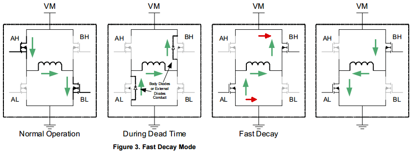
Note that in the picture on the right, those green arrows are only going in that direction for a very short time. They are very quickly reversed by the power supply and current now flows though the coil the other direction, making a reversed magnetic field, and continuing to rotate the motor. Also, "Dead Time" is very, very short. Oh, and the diodes are always there, but only shown when active.
Another way of managing the back EMF, called Slow Decay, is to actively short the coil to ground for a period of time between steps.
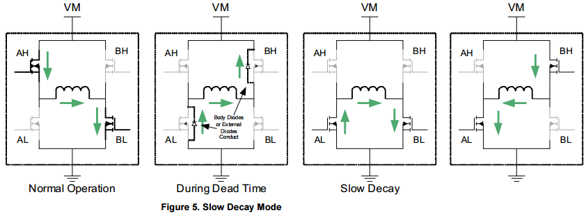
This is done by turning on the bottom two FETS for a fraction of a second. After that slow decay period, the opposite FETS are activated (AL and BH) to drive the next step, just like in fast decay. It's an extra, active shorting to ground, step in between the dead time and the next step.
Then there is "mixed" decay which is just a different timing of the shorted mode in Slow decay. In the THB6064AH, and most modern drivers, we always provide "mixed" mode, but the shorted time has different percentages from 20% to 80%.
So what's the difference? More shorting will reduce the "ripple" load on the power supply, but may cut into top motor speed because shorting doesn't reverse the current flow in the coil as fast as the power supply can.
And that was more than you wanted to know about decay!
So which mode should you use? No idea. Bottom line is just play around with it and see what mode works best for you.
| file: /Techref/io/stepper/decay.htm, 5KB, , updated: 2015/4/9 17:08, local time: 2024/7/17 12:35,
18.118.154.79:LOG IN
|
| ©2024 These pages are served without commercial sponsorship. (No popup ads, etc...).Bandwidth abuse increases hosting cost forcing sponsorship or shutdown. This server aggressively defends against automated copying for any reason including offline viewing, duplication, etc... Please respect this requirement and DO NOT RIP THIS SITE. Questions? <A HREF="http://piclist.com/techref/io/stepper/decay.htm"> Stepper Motor Driver Decay Modes</A> |
| Did you find what you needed? |
|
o List host: MIT, Site host massmind.org, Top posters @none found - Page Editors: James Newton, David Cary, and YOU! * Roman Black of Black Robotics donates from sales of Linistep stepper controller kits. * Ashley Roll of Digital Nemesis donates from sales of RCL-1 RS232 to TTL converters. * Monthly Subscribers: Gregg Rew. on-going support is MOST appreciated! * Contributors: Richard Seriani, Sr. |
Welcome to piclist.com! |
.