Microstepping Stepper Motor Driver Kit
Nothing is more valuable than feedback that honestly expresses what went wrong and what was done. From this type of selfless shareing of experience, others learn without cost. Many thanks for Mark for shareing his experience.
From this feedback, we can see how the LiniStepper design avoids damage to motors and its most expensive components even under massive overload and after user modifications beyond the recommended maximums. The components that fail first are low cost and easy to replace.
In general, information on proper use of the Linistepper is listed on the "using the Linistepper page"
There is also a nice thread at CNC Zone that shows how to trouble shoot the
driver. Note that this person did NOT purchase our kit and made his own PCB
so the failure in this case does not reflect on our kit
<GRIN>
http://www.cnczone.com/forums/showthread.php?t=10024&highlight=linistepper
casteelm-Remove- at frii.com asks:
Hello, love the kit and it works flawlessly (till I started playing with it of course), anyway I'm building a "power feed" for a milling machine, and my motor is of course big, I didnt expect to see it draw so much current at 100Hz and it appears I may have fried the pic, its ultimately biasing Q2, Q3 continuously. Can I buy a couple more pics? Also, I was thinking about adding on 2n3055's to up the capability, any negatives anyone can think of? THANKS! Mark
James Newton replies:
Mark, you're not supposed to let out the magic smoke! <GRIN> If you have a PIC programmer, you can buy the PIC's locally and use the code from the site. I'll make arrangements to send you a programmed chip if you can't. I don't think the 2n3055's will increase the ability of the unit to drive much more, see for more information.+
Roman Black replies:
Sorry to hear about your difficulties. :o)The linistepper is fairly hard to blow up, even if you short a motor connection it should still limit current to the correct current limit anyway! Provided it is wired correctly and has a big enough heatsink it should be very reliable.
Possible reasons for blowing it up would be;
- 5v regulated supply was not 5v regulated
- no heatsink (or too small) as the lini needs a big heatsink
- connecting a psu supply voltage backwards etc
- using too small value for current sense resistors (the lowest value allowed is 0.67 ohms)
Anyway i'm willing to work you through the repair if you can provide more information. :o)
- Please supply;
- motor ratings, ohms amps, volts etc
- psu ratings, volts amps etc
- the values for the big current sense resistors
- what you were doing when it blew
- what type and size of heatsink you were using
- type of regulated 5v supply you used
- how long it ran for
- any more info you can
The PIC should not be blown unless you have blown one or more output transistors. This would be hard as they are 100v 5A transistors and the kit is current limited at exactly 1 amp, so there is a 5x safety margin!
You worry me by mentioning "large" motor and the idea of using 2N3055's etc, the kit is sold as suitable for 1.5 amp motors and stepper motors draw exact current which is usually written on their label. It will run your large motor in perfect safety at 1A or 1.5A with the correct current sense resistors.
How much current were you trying to get? :o) +
casteelm-Remove- at frii.com responds:
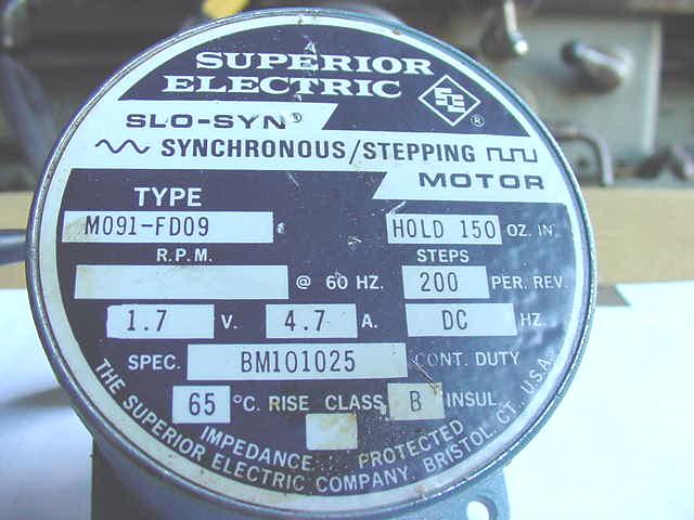
Hello guys! Thanks for your help!!! I guess first heres a couple links to pics that contain partial answers to your questions.Heres an ebay page link to the same motor that I'm using from this same guy. http://cgi.ebay.com/ws/eBayISAPI.dll?ViewItem&category=25286&item=3104731631 {ed: here is a picture of the back of the motor showing the specs} 1.7V 4.7A are indeed the same specs on my motor. I guess the ebay scrambled my brain and caused my to think this was in spec... 1st DOH!
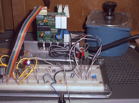
And heres a link to a pic of my setup. http://www.frii.com/~casteelm/Jan05.JPG {ed: local copy}
For heatsink I'm using the 4" length of 1/8" angle aluminum at the moment. I'm powering the 555 circuit and the 5V input to the linistepper from a 7805. On the high side its powered with a 24V 3A adjustable HP supply, The only mod I added was the two 0.47ohm power resistors in parrelel with the stock resistors as shown in the pic, the motor was absolutely gutless at 1.5A which was why I added the resistors.... this sounds like this was probably my problem... DOH! The combinatorial resistance shouldnt be less than 0.67? I was playing with different values of caps and pots in the 555 circuit to get my adjustable motor speed I wanted, when it popped, I was cranking it up to over 5KHz and the motor/circuit was just beginning to pull 3A, and I was running about 12 volts on the high side when it popped whatever in the circuit and then the fuse on the power supply. This did give me an idea just now, so I disconnected the linistepper, and powered up just the 555 circuit off the 7805, and cranked up the power supply voltage to 24v(yes I know the 7805 is only good for 18), but anyway, it doesnt appear to have lost regulation if indeed that did happen, the output of the 7805 remained less than 5.00 volts at all times it would appear so I dont think I had a powersupply overvoltage problem. The circuit had been run for probably half an hour off and on. As you can see in the pic I added 4 leds and resistors to the breadboard so I could see what the outputs were doing, I changed values in the 555 circuit down to about 1Hz so I could easily see whats going on, the outputs of Q2, and Q3 are stuck on. There appears to be no output from Q1, and Q4, this is without the motor connected, as the current draw is in excess of 4A now.
I measured all 8 transisitors with the diode check on my multi meter and get .6 between B and C,E on all of them and I believe all 8 of them are fine. I then began to question weather or not a winding of the motor shorted out, and its pretty inconclusive, my meter doesnt have enough resolution to tell, I get about .5 ohms between common and each leg, and anywhere from .5 to .8 between the other four wires which isnt seeming right at anyrate. I'm scrounging for another lower current motor as we speak just in case.
I dont have a pic burner, I'll ask around at work Monday, and again I'd still be more than happy to pay for a new pic to be burned since I'm sure it was something dumb on my part ;-D
Thanks again for all your help and going out of your way to help!!!
Mark
Roman Black replies:
Mark Casteel wrote:> > Hello guys! Thanks for your help!!! I guess first heres a couple > links to pics that contain partial answers to your questions.Hi Mark, thanks for the picture. Nice big motor. :o)
> 1.7V 4.7A are indeed the same specs on my motor.   I guess the ebay
> scrambled my brain and caused my to think this was in spec... 1st DOH!
Yep. :o)
> For heatsink I'm using the 4" length of 1/8" angle aluminum at the
> moment.
Ok, that's not a heatsink, that's a bracket. The heatsink should be a few times larger than that, it is easy to test, run the thing turning the motor fairly slow for 20 minutes and check that the transistors NEVER exceed temp 50'C, 45'C is better.
>   I'm powering the 555 circuit and the 5V input to the
> linistepper from a 7805.
Seems ok.
>   On the high side its powered with a 24V 3A
> adjustable HP supply,
That's probably too high a voltage. You have a motor using less than 2v. So you have 22v wasted as heat across the linistepper. Generally if you don't need real high speed performance the psu should put out about 3v more than the motor needs, the lini will run nice and cool. For your motor 5v main psu supply is fine, maybe 10v main psu if you need speeds over 5 revs/second.
>  The only mod I added was the two 0.47ohm power
> resistors in parrelel with the stock resistors as shown in the pic, the
> motor was absolutely gutless at 1.5A which was why I added the
> resistors.... this sounds like this was probably my problem...  DOH! The
> combinatorial resistance shouldnt be less than 0.67?
Yes the web page does show the max current as being 1.5A, and the minimum resistor value is also shown as 0.67 ohms TOTAL R COMBINED. Your resistor selection was giving about 3A per phase! Not only running the lini at double its max rating but you were running your 3A psu at 6A too! Wonder the psu didn't fail first, or maybe it did.
>  I was playing
> with different values of caps and pots in the 555 circuit to get my
> adjustable motor speed I wanted, when it popped, I was cranking it up to
> over 5KHz and the motor/circuit was just beginning to pull 3A, and I was
> running about 12 volts on the high side when it popped whatever in the
> circuit and then the fuse on the power supply.
Ok, you had the psu turned to 12v? That's ok but the motor would still draw from 3A min to 6A max depending which step it was on, with your resistor values. When running it would be the average, or 4.5A.
You CAN'T run the lini at double its max current with no heatsink dude! :o)
>   This did give me an
> idea just now, so I disconnected the linistepper, and powered up just
> the 555 circuit off the 7805, and cranked up the power supply voltage to
> 24v(yes I know the 7805 is only good for 18), but anyway, it doesnt
> appear to have lost  regulation if indeed that did happen, the output of
> the 7805 remained less than 5.00 volts at all times it would appear so I
> dont think I had a powersupply overvoltage problem.
That is good. The PIC may be ok.
>   The circuit had
> been run for probably half an hour off and on.  As you can see in the
> pic I added 4 leds and resistors to the breadboard so I could see what
> the outputs were doing, I changed values in the 555 circuit down to
> about 1Hz so I could easily see whats going on, the outputs of Q2, and
> Q3 are stuck on.  There appears to be no output from Q1, and Q4, this is
> without the motor connected, as the current draw is in excess of 4A now.
Ok, how to repair;
- replace all 4 of the BC337 transistors. About $1. DON'T be tempted to try to save some of them!
- then lift one leg of the 4 resistors R14 to R17.
- now the 4 main TIP122 transistors are disconnected completely and you can test to see which are damaged, some will probably be shorted in some way. My suggestion would be to value your time more than a $2 transitor and just replace ALL 4 TIP122s along with ALL 4 BC337s. (Cut each leg off first, makes them easier to desolder one leg at a time.)
The mode of failure was overheating, you ran 2x the max current and had very little heatsinking. I have had TIP122s running at over 120'C without blowing them, you must have got them WAY OVER their destruction point of 150'C. Either way if any of your TIP122 tests ok it was still subjected to some scary heat. Replace all 4. :o) I'm suprised you didn't see smoke coming off the thing!
>       I measured all 8 transisitors with the diode check on my multi
> meter and get .6 between B and C,E on all of them and I believe all 8 of
> them are fine.
They won't be. If they were fine the lini would still be running. Nothing else can blow until a TIP122 blows first, as everything else is at 5v regulated and low current. It's the beauty of the lini design, only the TIP122 collectors are at main psu voltage. BUT once once a TIP122 blows to a short circuit the main psu voltage can get to the other parts. :o(
>   I then began to question weather or not a winding of
> the motor shorted out, and its pretty inconclusive, my meter doesnt have
> enough resolution to tell, I get about .5 ohms between common and each
> leg,  and anywhere from .5 to .8 between the other four wires which isnt
> seeming right at anyrate.  I'm scrounging for another lower current
> motor as we speak just in case.
I looked at your picture, that motor would have run 5x cooler than the lini, and motor is rated for about 90'C anyway. Your motor is ok.
The lini is fully protected against motor short circuit coils too, it will just regulate the current to the right amount. :o)
> I dont have a pic burner, I'll ask around at work Monday, and again I'd
> still be more than happy to pay for a new pic to be burned since I'm
> sure it was something dumb on my part ;-D
I must agree. <friendly grin>
Once you have replaced all 8 transistors, and put the main resistors back to the original 1 ohm values, it should work ok and turn your motor again.
If it doesn't, it's possible the 12v main psu got through a shorted TIP122 and blew the PIC one or more pins on PORTB. This is VERY unlikely, because at 12v pins RB4 to RB7 have 340 ohms in series so the current would be limited to 12v - 5v = 7v /340 = 20mA and pins RB0 to RB3 have 1k5 in series, so 5mA.
The PIC SHOULD be ok. I'll bet money you have dead transistors, replace all 8 and it's fixed. :o)
> Thanks again for all your help and going out of your way to help!!!
> Mark
No drama Mark, I know James will probably put this up on the page and it may help others.
Now once you have it fixed and running at 1A (properly with a big heatsink!) email me back and i'll try to get a solution to run that big motor better or maybe suggest a better motor alternative. :o)
-Roman
Another case:
Just wanted to pass on my thanks for the help from both of you in regard to my messge about my vibrating motor problem. I also wanted to tell you what was wrong in case it helps someone in the future.I thought that Q5 was dead from my analysis of it with a meter, but after replacing it (having two friends help with their own soldering irons so as not to have to cut it off first in case it wasn't damaged) with one of your suggestions, it still did the same thing. I was "defeated" and pretty stressed about my upcoming need for the motor driver this weekend and not having the resources to rush-ship another kit (if you even do that).
In any case I began looking for anything I had missed when inspecting the board and then began just checking that there was continuity between the ends of the circuit board traces. In the case of Q5 - there was not - though it did not appear to be solder-damaged or any other visible reason why the connection wasn't good - but the base of Q5 and the heat-sink side of R7 were not connected so I jerri-rigged a short piece of insulated wire from the base of Q5 up and over to R7 and low and behold - IT WORKED! :)
thanks again!
-george
Interested:
Questions:
Comments:
I have just had a really stange fault. I built a couple of Linistep drivers and they were working really well. However i decided to see if i could get things running at 24V and again all went well for a while but then I found a little problem. One of the transistors was not seated as well as it should have been and heated up melting the insulator.James Newton of Massmind replies: It's quite possible that the PCB was damaged by the heat or excessive current as the driver melted down. Check the PIC power supply, and the traces from the xtal or any other critical pins (MCLR, etc...)+
The fault i am getting is that in Mach3 the motor only steps once if i jog forward and backward several times.
I replaced all Caps, Transistors, the PIC and even the xtal just because.
However the problem persists. Its almost as if the PIC is not running (the new, old or other unit) I also tried a diferent computer just in case there was an issue with the paralell port but I still have the same issue.
Unfortunalty i do not have a scope so can not see what is going on.
Any sugestions would be appreciated
Andrew S Hooper replies: Well Don't I feel stupid. The problem was not the boards, somehow I had inverted the step line with the DIR line on the cable coming from the PC. After having the same problem with all 3 boards and not with the test board and stripping the first down to just the resistors i build an independent test circuit on a protoboard so as to be able to test the PI and have LED's to show me what was going on. I then put the problem boar in parallel with the test circuit and discovered the problem or rather what I had done. The symptoms of this however are not as clear as would be expected. If you hit the JOG key sever time in one direction then several times in the other you sometimes get a step hence why it looked intermittent. Hopefully this may save someone else a few hours of fault finding in the future :) +
| file: /Techref/io/stepper/linistep/blown.htm, 20KB, , updated: 2009/8/10 14:01, local time: 2024/8/14 09:47,
owner: size111-hotmail-,
3.16.130.242:LOG IN
|
| ©2024 These pages are served without commercial sponsorship. (No popup ads, etc...).Bandwidth abuse increases hosting cost forcing sponsorship or shutdown. This server aggressively defends against automated copying for any reason including offline viewing, duplication, etc... Please respect this requirement and DO NOT RIP THIS SITE. Questions? <A HREF="http://piclist.com/techref/io/stepper/linistep/blown.htm"> How to blow up the Linistepper (or avoid doing so)</A> |
| Did you find what you needed? |
|
o List host: MIT, Site host massmind.org, Top posters @none found - Page Editors: James Newton, David Cary, and YOU! * Roman Black of Black Robotics donates from sales of Linistep stepper controller kits. * Ashley Roll of Digital Nemesis donates from sales of RCL-1 RS232 to TTL converters. * Monthly Subscribers: Gregg Rew. on-going support is MOST appreciated! * Contributors: Richard Seriani, Sr. |
Welcome to piclist.com! |
.