First all plastic is removed around the C84 that is not required for printing. This is the side caps, the main body, and some smaller loose bits. At this point the printer will still print normally.
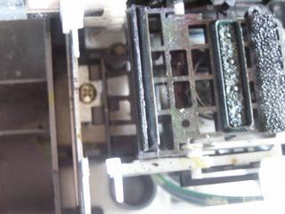
make sure the printer is in good working order, and the parking station is clean. With all used C84s you will find a badly clogged parking station/vacuum mechanism that MUST be cleaned. See:
Do a nozzle check to make sure the head is working on all nozzles. I opted to disable the vacuum mechanism by removing the small gear on the rough transport roller and instead manually provide vacuum with a syringe. You can leave the pump engaged if you do not mind unnecessary cleaning.
 This is also the best point to install
spongeless
cartridges^ with
auto-reset
chips^ and test them on paper. Fill yellow MISPRO ink in the
black cart (you may also use the yellow cart; the C84 can not tell which
cart is where as long as all are present). Add a few drops of black MISPRO
ink for better visibility.
This is also the best point to install
spongeless
cartridges^ with
auto-reset
chips^ and test them on paper. Fill yellow MISPRO ink in the
black cart (you may also use the yellow cart; the C84 can not tell which
cart is where as long as all are present). Add a few drops of black MISPRO
ink for better visibility.
Volkan says: "You need to use MIS PRO yellow or magenta; both are working but yellow is the best etch resistant. I use yellow (in cyan and yellow cartridges), magenta (of course in magenta cartridge) as a media glossy photo and as a printing color 'color black' {which mixes the colors to make black, using all the cartridges, and reducing issues with a single clogged nozzle}. "
 The paper feeder is removed from
the back, taking out the optical paper sensor.
The paper feeder is removed from
the back, taking out the optical paper sensor.
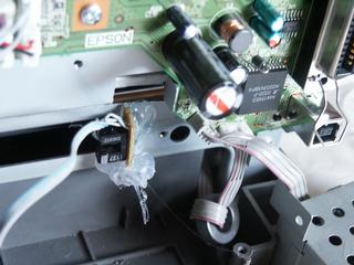 This sensor is glued to the side
of the paper slot (in the metal chassis), so that the material passing through
here will activate it.
This sensor is glued to the side
of the paper slot (in the metal chassis), so that the material passing through
here will activate it.
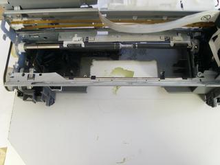
 Remove the pizza wheels from the output. You
may also remove the black plastic paper guide and that ink sponge at the
front. Rip out the whole spiel, you only need to keep that greased sheetmetal
rail where the head rides on. It is easier to leave the shaft with the rubber
output rollers in place since it carries a pulley for the belt. It has no
further function and you could remove it if you tension the belt some other
way. Now a flat sheet will pass through the printer.
Remove the pizza wheels from the output. You
may also remove the black plastic paper guide and that ink sponge at the
front. Rip out the whole spiel, you only need to keep that greased sheetmetal
rail where the head rides on. It is easier to leave the shaft with the rubber
output rollers in place since it carries a pulley for the belt. It has no
further function and you could remove it if you tension the belt some other
way. Now a flat sheet will pass through the printer.
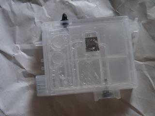
![]() Remove the middle pressure roller
assy. Now a small PCB will fit through the middle. If you cut it in half
and replace the outer pressure rollers with the half sections you get even
larger PCBs through. You must hold the springs up with something like a strip
of metal or PCB to make up for the cut-away half. If one needs full with
even narrower wheels could be attached at the very outside, but usually it
will not be needed. If you go for a rail under the carrier for 2-sided PCB
alignment you need to take out the rough transport roller and grind it down
in the middle to allow this rail to pass. Works well with a bench grinder.
Don't grind it too thin you need some strength.
Remove the middle pressure roller
assy. Now a small PCB will fit through the middle. If you cut it in half
and replace the outer pressure rollers with the half sections you get even
larger PCBs through. You must hold the springs up with something like a strip
of metal or PCB to make up for the cut-away half. If one needs full with
even narrower wheels could be attached at the very outside, but usually it
will not be needed. If you go for a rail under the carrier for 2-sided PCB
alignment you need to take out the rough transport roller and grind it down
in the middle to allow this rail to pass. Works well with a bench grinder.
Don't grind it too thin you need some strength.
If you use very thin PCB material (60mil / 1.5mm) you can skip this section, but to allow for the increased media thickness we must adjust the head height. The easiest method i found is to cut through the chassis just over the paper gap. You could cut exactly through the paper gap, but that would lift the pressure rollers as well and require a change there. The chassis can be cut in place with nibbler pliers.
 On the left (stepper/belt) side of
the printer you need to add a small piece of sheetmetal (ideally an angle
piece around the rear edge) that holds the cut-off part at about 3mm higher
than it originally was.
On the left (stepper/belt) side of
the printer you need to add a small piece of sheetmetal (ideally an angle
piece around the rear edge) that holds the cut-off part at about 3mm higher
than it originally was.
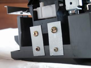
![]() On the right (head) side you can simply put
nuts or washers under the two mounting screws (and use longer screws) to
achieve the same increase in head height.
On the right (head) side you can simply put
nuts or washers under the two mounting screws (and use longer screws) to
achieve the same increase in head height.
 CENTER |
You also need to raise the head parking station, lift up the plastic over the screw mount on the inside and again use a piece of plastic or sheetmetal with screws to raise it on the outside. There was a snap-in mechanism originally not allowing you to simply put something under a screw. The inside is not held as firmly now, but that's fine and you could use a longer screw and some strip of metal to clamp it down if you really like.
 FRONT RAIL |
Lastly you need to raise the front head rail by the same amount. Simply put spacers (nuts) under where the screws attach the piece and use longer screws.
 TOP |
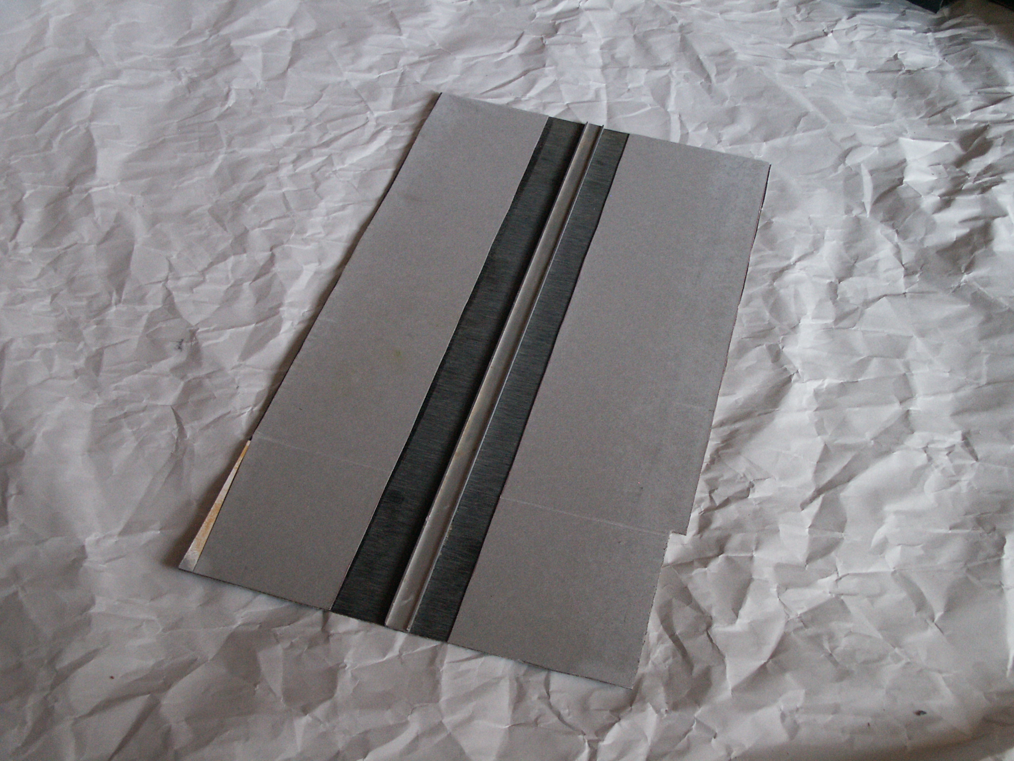
You need to make a carrier for your PCBs, any rigid material like cardboard will work. It should not be too heavy. I used a sheet of formica and glued thin cardboard to the bottom for traction (probably not needed). If you want a rail for alignment you can glue a piece of aluminum to the carrier. It must be low in height to fit in the gap in the transport roller, but high enough to provide alignment between plastic guide rails. If you do not need the rail a simple piece of cardboard will do.
The C84 will expect a short delay between the start of the feeding mechanism and activation of the paper switch, so you need to make a cutout of 3.54inches / 90mm on the carrier to facilitate this delay. That is with the sensor right at the metal, if you place it further outward you need a longer cutout. The C84 is quite tolerant, a tolerance range of about +-4cm or so was found to work.
If you need to align printing on the second side of the PCB it would be good to be able to print in the same spot each time. To ensure that you can put a rail on the underside of the carrier which rides between plastic guides on both the input and output of the printer. To mount these plastic guides it is easier to cut out the plastic bottom of the printer to allow for wooden mounting blocks. I have not yet installed this fully as aligned doublesided printing is not a priority.
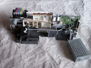
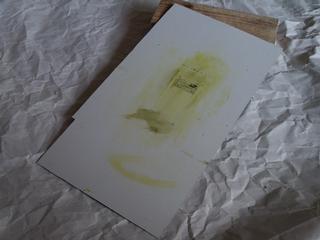
 Here is a nice shot of the final
modified C84 ready to print. The guides are mocked up in this photo, but
have been completed as planned.
Here is a nice shot of the final
modified C84 ready to print. The guides are mocked up in this photo, but
have been completed as planned.
Questions:
Comments:
Thanks for the article.... must give it a try one day, emm wonder if it'll work with the chepaer Epson's.
Don't know why there's non made commercially... hey you could hit the big time here by going in production, cheers and thanks
David
Leigh, Nr. Manchester
UK
Code:
| file: /Techref/pcb/etch/c84-st.htm, 15KB, , updated: 2022/5/24 18:00, local time: 2024/10/6 02:10,
18.216.133.165:LOG IN ©2024 PLEASE DON'T RIP! THIS SITE CLOSES OCT 28, 2024 SO LONG AND THANKS FOR ALL THE FISH!
|
| ©2024 These pages are served without commercial sponsorship. (No popup ads, etc...).Bandwidth abuse increases hosting cost forcing sponsorship or shutdown. This server aggressively defends against automated copying for any reason including offline viewing, duplication, etc... Please respect this requirement and DO NOT RIP THIS SITE. Questions? <A HREF="http://piclist.com/techref/pcb/etch/c84-st.htm"> Direct to PCB InkJet Resist Printing Modifications for Epson Stylus C84 by Stefen Trethan</A> |
| Did you find what you needed? |
|
o List host: MIT, Site host massmind.org, Top posters @none found - Page Editors: James Newton, David Cary, and YOU! * Roman Black of Black Robotics donates from sales of Linistep stepper controller kits. * Ashley Roll of Digital Nemesis donates from sales of RCL-1 RS232 to TTL converters. * Monthly Subscribers: Gregg Rew. on-going support is MOST appreciated! * Contributors: Richard Seriani, Sr. |
Welcome to piclist.com! |
.