SECTION 2 Writing Code for the PIC
CHAPTER 5
I wanted to build a bike computer as an exercise to learn how to program
in Assembly language as I explained in Chapter 1.
As always I start out by making a flow chart which is empty. Of course if
I had known what to put into it then, well I wouldn't have needed to learn
how to write the PIC code.
Let's say at this stage the flow charts are either very empty or meaningless.
Best leave them till the end of the project. They look nice.
So a good starting point is do a little theoretical exercise where we speak
about what features a bike computer should have, do the maths of each feature
and try and define further at each step, the bike computer itself. Really
we are identifying functional blocks which then, if feasible, can be turned
into PIC code.
* What follows is very large, in that the bike modules identified are many...
maths, speed , distance, time HP, calories,
Angle, friction, wind speed….. these are all possible, and the PIC has
enough input ports to handle the sensors. There is one basic problem.
The resulting PROGRAM IS TOO BIG FOR THE PIC 16F84A. So the original notes
stop at the point where we have identified the basic features of the bike
computer.
Within this limiting of the features, YES, the PIC can handle the resultant
size of the program.. ( I haven't got a crystal ball, I ran into the problem
and there is no getting round the code-too-big for the chip memory
limitation).
I have no doubt that optimizing the code ( it becomes very illegible when
optimized ) we could squeeze in the wind function. But when we arrive at
the situation that we are at a memory limit and that we are running out of
variable space, it would be better to move upwards to a bigger PIC, compatible
as far as possible with the code we will write.
The First attempt to define the bike
computer
Sorry if the way it is written rambles… but at this point there was
just an idea and questions about how to give it form…. So please bear
with me and don't laugh as the original mistakes have been kept in. For example,
the wheel distance for one revolution s taken as 4m when it should be 2m.
Anyone spot the mistake?
Start of my original notes
…. the operations , data and the
constants needed for the complete bike program.
THE INITIAL STARTING CALCULATIONS AND DATA INPUTS
Wheel circumference= Radius*2pi (for a 26" wheel circ=26*2*PI*2.54/100 =
4.14m)
constant for diam. to distance is 4.14/26 =0.156. So this is a START calculation
and is stored
in DATA memory as a the wheel circumference.
DATA memory will also need to have in kg
The rider weight =wrid and the bicycle weight = wbike. So total weight wrid+wbike
= wtot
wtot for example calculations =85kg +15kg =100kg
Wind resistance can be calculated as a function of bike speed, more later.
Road friction can also be calculated when the bike type ( road or mountain)
is entered and the
appropriate equation selected..
But maybe there is a better way, the "flat road time to come to rest
measurement"
THE WHEEL
Wheel circumference is an initial constant which by now has been entered
for a given bicycle.
In the EXAMPLE a 26 inch wheel has a circumference of 4.14 m. So as explained
above circ=4.14
and is needed,, to calculate ALL OF the following a)... e) .
a) Trip total dist. sum of wheel pulses
b) Average speed dist / time
c) instantaneous speed dist / 1 sec
d) peak speed. highest recorded value of c)
If we sum a) to the previous total of distances from previous trips,, this
gives the
e) Total kms the bike has covered since the computer was installed.
DISTANCE
Each circumference travelled is one wheel revolution. So the magnetic
sensor
will generate a pulse per revolution. In this case 1 pulse every 4.14m. and
thus the wheel constant
is 4.14m =circ
So to calculate a) we need to store the total of wheel pulses and multiply
by 4.14. Store in
the Wheel Pulse Register
The result in meters is usefully displayed as km to two decimals. This means
that we can view the
trip distance to within 10m. A 5 digit display gives a maximum trip distance
999.99 km,, so we will need
a five digit LCD display.
TIME & STANDARDS
To calculate b) we need to know the time that has elapsed. The STANDARD that
generates
the time,, our local CLOCK has to have sufficient accuracy for this task
How accurate?
We have three available standards for the PIC. Xtal,, ceramic resonator,,
and RC.
Consider the RC. Well a one second a hour error at 15km/hr means a distance
error of 4.14m
or in 100km 414m error, about half a km....an error of 0.5%.
This is probably a practical measurement limit,, tyre pressure,, skids,,
bumps,, wind, slope.... will all
tend to produce worse errors. If we want real DISTANCE ACCURACY we can use
GPS measurements
So at first sight any standard will do,, we could use the RC network.
The 4MHz xtals are very stable and theoretically will allow in the same
circumstances at 15km/hr an error in
dist /time measurement to be only a cm and time a fraction of a second.
But the other uncertainties mean that in practice you can't use the accuracy.
If we want the time STANDARD as a WATCH. days, hours minutes seconds... we
may have to come back to this.. .
Lets look at the third option.
A ceramic resonator is small and offers a 1in 10000 precision and also a
low frequency, say 32000Hz
We divide by four to get the machine cycle. We get two bonus points
The error is OK for a TRIP display,, 1 second error in 3 hours.
This is also very good for reducing the power consumption of the PIC and
peripherals.
However it may be too slow as it limits the PIC to 8000 machine cycles /per
sec!!!
We will use for the timing example 8000Hz = 0.125msec per cycle.
PIC System clock is 0.125 millisecond
On starting the computer we need a time elapsed counter for total trip
time.
What could a maximum trip time be? Let's say 24 hours.
24 hours in seconds is = 86400 seconds
24 hours in machine cycles is =691,, 200,,000 Can the PIC manage this quantity?
Note find timer example on the internet.
Of course we limit the count to one hour =28,,800,,000 and increment a register
in steps of 1. This
would be the hour register.
We can now calculate b) Average speed from Wheel pulse Register / hour
register
To calculate c). Instantaneous speed we need to measure the time between
consecutive
pulses from the wheel,, by reading the number of clock pulses before the
2nd pulse is detected.
An example could be that the second wheel pulse arrives 6000 clock cycles
after the first.
So we can calculate the instantaneous speed as :-
8000/6000*4.14*3.6 = 19.872 km/hr at that moment.
Store the value in the instantaneous speed register
We have to do Two things with the Instantaneous speed . Let's look first
at the easiest....
The instantaneous speed value is displayed and also internally this value
is compared with the
previous value stored in the max speed register. This will give us d) peak
speed
The condition is "If greater than stored value,, replace with actual
value."
The second thing is a know problem because the speed display is constantly
dancing
and visually this is annoying. So we need another routine to sum the last
five seconds and
show the average instantaneous speed. This means we need to reserve a chain
of
FIVE instantaneous speed registers. This routine will have to sum reg1,,
2,, 3,, 4,, 5 and
divide by five. The result is then displayed as instantaneous speed. It will
also mean a shift
routine to keep the data moving, always losing the oldest reading.
There remains d) total km since installed. FROMDAY1 register should probably
be
increased by 1 for every measured km covered during the trip which is in
progress.
(I say probably because maybe
there is an easier way of showing bike's total km????)
wake up
On wake up you have last trip data still available.
If you wish to retain previous trip data .....do nothing with button B.
Note. You may want this to sum total km in a day after stopping to eat.
If you wish to start afresh.....
Reset to zero, distance, time, average speed, maximum speed, Calories
burned… by holding down button B for five seconds.
Display 1 will show Speed and Trip distance to nearest 10m.
Pulse A
Display 2 will show Average speed and Trip time. to a maximum of 24 hours
Pulse A
Display 3 will show Top Speed and sum of all trips distances to a maximum
of 99,999 km
Pulse A
Display 4 will show present HP and kCal/km at present rate.
Pulse A
Display 5 will show Peak HP and integrated trip kCal burned.
Pulse A
Display 1 will show Speed and Trip distance to nearest 10m.
We now move on using the above description to try and
create the needed modules.
The above shows how idea has been captured my style, and translated into
Maths equations.
We are going to change the rough outline and the equations into code blocks,
but first we need to answer some basic questions as to what instructions
exist and also to get our tools working.
-
First question: where are multiply, divide, sin, trig
instructions. ? You quickly discover that in Assembler and with a simple
chip like this, they don't exist.
-
Second question Can we handle decimal fractions. Answer
yes… but with a lot of routines written for one's own specific
application.
-
Third question. Surely someone will have written something
similar, why reinvent the wheel? Yes, but adapting or grafting is not any
easy task. Also many ideas written in code are just that, ideas that have
never been tested..
So let's sort out the initial problems and get started with the code.
Our program to run the PIC code and then send it to the 16F84A is MPLAB,
but if we have never seen it before we may have problems in setting up the
initial options. MPLAB presuppose that you have done some programming, but
this is not necessarily true. I hadn't, and I floundered for a bit till I
discovered that MPLAB need two basic inputs to work.
-
Our assembler program
-
A project.
I didn't see this at first. If you haven't created a project, them the assembler
code can't be run. And of course the other way round. If you have created
a project but have no code written , then there is also nothing to run. In
both cases MPLAB waits…
So out project is called Bike3.pjt (MPLAB adds the extension). But so that
we can see the essential screens lets briefly open a NEW project. A reasonable
name would be Firsttest.prj ( MPLAB will toss the name out as it has more
than eight letters, but Firstest is OK as it is inside the maximum. Try both..
Ah before I forget, we will put this firstest.prj in my PICproj directory,
which starts empty so that we can see the files that MPLAB is generating
for us. So run MPLAB and go to the second menu Project, select New and we
have an invitation to name the project.
Fig 20 Naming the project
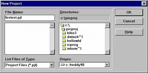
We enter the wrong name(9char) “firsttest” and get the message,
“too long”
We enter again but with one “t” less. MPLAB accepts and opens the
next window below fig.200 We can see that firstest.hex has been written in
two `places by MPLAB. Fine, we will come to that a little later. The essential
thing that MPLAB need to know is what kind of Chip are we going to use and
what features will we employ. . These details have already been chosen by
me as we see IN WINDOWS MPLAB SIM PIC16f84A and also LANGUAGE TOOL
SUITE has been chosen as MICROCHIP
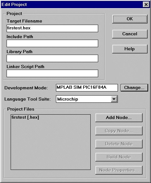
fig. 200 Project box
How did I do it? Well if we look a little further down fig.200 we see a button
labelled Change..
Pressing it takes us to the next menu in fig.201.
Fig.201 asks for details such as the ones we have just mentioned and more.
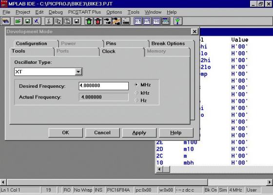
We click the tags
We enter XT and 4.000000, not forgetting to tick MHz as well.
Configuration tag next. Enter watch dog timer none and postscale 1. Processor
mode, microcontroller-
Break tag. Clear, global, freeze. Finish with APPLY .
Now here MPLAB warns something about a hex file which at this moment doesn't
seem to make sense. If you know what is going on fine, but if you don't it
is a bit mysterious and you may feel you hit the wrong key to leave the menu
fig. 201
No you did it OK. MPLAB is worried because it has no assembler file, ( it
is looking for a file called firstest.asm, which we haven't yet entered)
and from that reason it tells you that it can't go on..
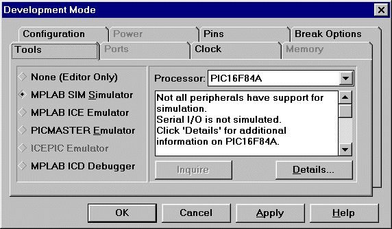
fig.201 Mplab messages
fig 202 options dev mode
So we return to fig.200 to clear up this problem that MPLAB has. How?
Well please remember all this is dummy, so that we can play a little with
the menus.
We can create another dummy firstest. asm
And see what happens.
To do this we go to the top menu again
and open FILE, New.
Write anything in it, I wrote “First time.”
Then save in the PICproj directory as firstest.asm. We then go back to the
project menu and see what MPLAB thinks about the Firstest.asm file we are
going to offer it. Here goes. We change to the project menu and at the top
we see that firstest .prj is still open. Good. ( But if it wasn't? Then use
Open Project from the dropdown menu or simply click it from the list at the
bottom.)
So we have our project open but as yet no Firstest.asm to feed to MPLAB.
The only button not “Greyed Out” and which we haven't touched is
Add Node. This is MPLAB_speak for “find me an assembler file to play
with”.
So we press Add Node and enter from the PICproj directory firstest.asm.
( If MPLAB offers you a different directory in the previous step, change
with the browse button. Somewhere I read that the project and it's xxxx.asm
files have got to be together)
Yes , fine MPLAB accepts our dummy firstest.asm file. And adds it to the
project window.
Note I'm playing about with capital and small letters for the file names.
Be careful. In some places MPLAB doesn't care a hoot, in others it gets really
shirty.
So we seem to have deceived MPLAB giving it a dud asm file. Well not really,
but up to here it has enabled us to test the main buttons and set up MPLAB.
We have achieved our aim and have a file which MPLAB can do something with.
It can run the code we have written in the dummy file firstest.asm ( remember
we wrote “ First Time”) . Well to get MPLAB to attempt to do something
with it , in the project menu, we try another button called “BUILD
ALL”
Yes indeed something happens , MPLAB spits out the following
Building FIRSTEST.HEX...
Compiling FIRSTEST.ASM:
Command line: "C:\ARCHIV~1\MPLAB\MPASMWIN.EXE /e+ /l+ /x- /c+ /p16F84A /q
C:\PICPROJ\FIRSTEST.ASM"
Error[122] C:\PICPROJ\FIRSTEST.ASM 1 : Illegal opcode (time.)
Error[125] C:\PICPROJ\FIRSTEST.ASM 2 : Illegal condition (EOF encountered
before END or conditional end directive)
MPLAB is unable to find output file "FIRSTEST.HEX".
Build failed.
The last line says it all, “build failed.”
But it doesn't matter. We have set up MPLAB for a PIC 126F84A, running at
4MHz and it is attempting to compile.
From here on, we can forget about setting up MPLAB and concentrate on writing
code. There are lots of other things it will do but we are over the major
hurdle in getting the MPLAB program started.
If all this is boring you stiff, skip the next
bit, but as this is written for beginners like myself who get stuck on the
most obvious things initially, we will try and explain all that is needed
to make MPLAB happy with our dummy asm file.
Well MPLAB replied to our first compile attempt with “build all”
….and blew us a raspberry.
But it also gives clues to where it is wrong, or things missing.
The last line seems worried about the end do we need to add and end? Yes.
Well let's add the word end.
How? Well there is a window open showing our Firstest.asm file. If you haven't
got that window open. , go to the file menu and open it.
Then simply write the word end at the end to see if MPLAB feels a little
happier. Compile with Build all in the project menu once more. We now get.
Building FIRSTEST.HEX...
Compiling FIRSTEST.ASM:
Command line: "C:\ARCHIV~1\MPLAB\MPASMWIN.EXE /e+ /l+ /x- /c+ /p16F84A /q
C:\PICPROJ\FIRSTEST.ASM"
Error[122] C:\PICPROJ\FIRSTEST.ASM 1 : Illegal opcode (time.)
Warning[205] C:\PICPROJ\FIRSTEST.ASM 2 : Found directive in column 1. (end)
MPLAB is unable to find output file "FIRSTEST.HEX".
Build failed.
Still grumbles about end but something changed,
it doesn't like it in column one. So move it to column two ( shift key or
simply spaces).
Compile again with build it….
Building FIRSTEST.HEX...
Compiling FIRSTEST.ASM:
Command line: "C:\ARCHIV~1\MPLAB\MPASMWIN.EXE /e+ /l+ /x- /c+ /p16F84A /q
C:\PICPROJ\FIRSTEST.ASM"
Error[122] C:\PICPROJ\FIRSTEST.ASM 1 : Illegal opcode (time.)
MPLAB is unable to find output file "FIRSTEST.HEX".
Build failed.
Eureka!!!, the error message about the end has
gone. Next thing is our text which is not an instruction… maybe we could
recycle it as a comment. to the right of ; comments are ignored. (A comment
begins with a semicolon).
Try it, compile again…..
Building FIRSTEST.HEX...
Compiling FIRSTEST.ASM:
Command line: "C:\ARCHIV~1\MPLAB\MPASMWIN.EXE /e+ /l+ /x- /c+ /p16F84A /q
C:\PICPROJ\FIRSTEST.ASM"
Build completed successfully.
We are there. MPLAB gave us the green light. Also
the message at the end
MPLAB is unable to
find output file "FIRSTEST.HEX".
about “can't find the hex file” has gone. Why? Well it must be
MPLAB's diplomatic way of saying, “I'm not going to produce a HEX file
with that load of rubbish code”, when it finds syntax errors.
Just before we forget , save the project for next time using “save
project” then “close project” ( project menu). We can now
examine a little further, we were saying….
On the other hand we have compiled an absolutely useless piece of code. How
is this possible? We agree it is useless, but MPLAB accepts it because it
doesn't break any rules. …. There are no syntax errors.
You mean that you can compile something that is wrong? Well normally not
something so absurd as out little asm file, but how do we define the word
wrong?
Someone told me a long time ago….
A computer does what you tell it to do,
Not what you thought you told it to do
It is still true today. Providing what you write meets the rules, it's fine
by MPLAB and by extension we have something to pass on to the PIC. Useless?
No, we are trying to test all our tools.
In our PICproj directory, we see…
firstest cod 3.072 11/03/02
13:28 FIRSTEST.COD
firstest err 0 11/03/02 13:28 FIRSTEST.ERR
firstest lst 680 11/03/02 13:28 FIRSTEST.LST
firstest pjt 1.482 11/03/02 13:51 firstest.pjt
firstest asm 20 11/03/02 13:28 firstest.asm
firstest $$$ 19 11/03/02 13:21 FIRSTEST.$$$
firstest hex 13 11/03/02 13:28 FIRSTEST.HEX
7 archivos 5.286 bytes
MPLAB has indeed been working, three of the seven we recognise immediately
maybe above all the firstest ,hex file which is what we need to run the PIC.
What to do with the HEX file
Before going on, let's open up the project again and press
the Project then, project Edit buttons. The bottom button in the window that
opens is called Node Properties, but is greyed out. Click on firstest.hex
and the Node properties become alive. Click on it and here we have a whole
host of things to fiddle with.
Leave them alone for the moment as they are the default settings established
by what we have entered earlier and in part by what MPLAB thinks is
“Normal”
Look at the HEX FORMAT row. We are offered three possible formats. We haven't
chosen any of them. Can we leave it like that? Well the short answer is yes.
But be aware that extension. HEX is not universal and comes in different
flavours.
In our case we are going to use ICPROG next, to get the hex file into the
PIC, and fortunately we find that ICprog is happy with the default output
of the PIC.
But if you use something other than ICprog, this may not be the case.
Icprog wants to know above all
fig.21programmer type
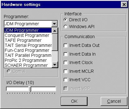
what kind of test card is holding the PIC and you tell it which by choosing
from the list options shown in the settings, hardware settings, menu that
is open in fig 21.
The other options that a different programmer could need to have changed
are listed on the right under the heading communications.
In my case I selected the JDM programmer from the list, and COM2 The list
also is useful in that it is a list of programmers that will work with
Icprog.
So having set up ICPROG to work with our programming card, we then open the
Hex file in PICproj directory.. Now as this is just a comment, we will not
program a PIC, but we will exercise the COMMAND menu fig 22
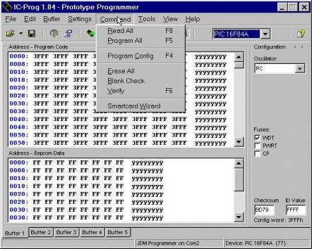
First we load from the PICproj directory “firstest.hex”, then as
supposedly we have a PIC 16F84A inserted in the programmer card, we check
that it is blank. . press Blank check.
After a few seconds we should see confirmed blank, OR, that it has data stored
in the 16F84A. ( In real life , maybe we used the PIC before for another
version or program).
fig.22 COMMAND menu
If the PIC is found not to be blank, then we need to wipe
it. With ERASE ALL option in the command menu.
Here there are only two possibilities, it gets wiped or data remains. How
can this be if we have just the ERASE ALL command? Yes, good question. If
you program the PIC more than about the minimum 1000 times, well it is possible
that the Flash programming stops responding in some cells. Then what? Best
find another PIC.
In the other normal case, we get the message “ Device is blank”.
Then we can move our hex file into the PIC clicking the COMMAND, PROGRAM
ALL buttons.
Icprog then programs the PIC and does a verify at the end to make sure that
what is in the PIC is the same as the hex file.
However we sometimes are not sure which hex file we have in the PIC at that
moment. So we can do a recheck.
-
Load the firstest.asm file
one again from the PICproj directory.
-
Look at the bottom line to see which buffer tag is active.
( probably one)
-
Click on another buffer tag, say two
-
Click COMMAND, READ ALL which will put the PIC contents
into buffer two.
-
Change to the buffer menu, compare 1 with 2
-
If they are the same we see “ buffers compare
successfully”, and we know that the PIC has been programmed correctly
-
If not the same. , click Command, Erase all. And reprogram
with
-
COMMAND, PROGRAM ALL.
The dummy program Firstest.asm has enabled us to use many menus in the chain
that takes us from untested code to compiled code and putting it into the
PIC . In other words, we have tested a complete chain. So now we will test
a simple module to learn a little more about what the PIC expects


