
UBICOM Prototype Adapter
Design Challenge and Contest
The SX 48/52 was (is) a monster chip (4K code space, 262 registers, 4 to
5 - 8 bit IO ports, 2 16 bit timers!) but despite all that it went
mostly unused among experimental users. Why? I don't think it was the chip
cost... they have been available for $7 to $12 dollars in single quantities.
-
It was only available as a Surface Mount Part. Many people don't have (or
don't believe they could have) surface mount soldering skills. (or they don't
want to hassel with it.)
-
The available adapters or demo boards are either expensive or bulky and don't
allow for the easy replacement of fried chips.
Now Ubicom is releaseing the IP 2022. If you thought
the 48/52 was killer, check out these stats:
-
Code Space: 64K FLASH, 16K SRAM
-
Data Space: 4K SRAM
-
Operation: 100MIPS (from a 4Mhz clock via PLL) at 5.5 Volts or 50 MIPS at
down to 2.5 Volts. Speed instruction for on-the-fly execution speed changes.
Sleep with independant RTC wakeup. Brown-out and watch-dogs.
-
Timing: 1 - 8 bit Real Time Clock and 2 - 16 bit PWM/Capture/Compare and
prescalars with 3 cycle interrupt handeling
-
Interface:
-
Analog: 10-bit, 8-channel, 48 kHz and a differential comparator with hysteresis
-
Serial: Two pairs of general purpose programmable serializer/deserializers
for 10BaseT (MAC/PHY), USB, etc...
-
Parallel: 52 IO Pins, 8 for external interrupts
-
and don't forget the 2 - 16 bit PWM/Capture/Compare and prescalars
-
GNU tool chain support, code for full TCP/IP stacks, email, web servers,
I2C, SPI, RS232, etc...
-
Price: $13.30 in quantitys. Offered (only) in an 80-pin plastic quad flatpack
(PQFP) package.
We need an adapter for this monster chip so that we don't miss out like
we did with the 52.
What sort of adapter can we make? What was available for the 52 and what
can we learn from the mistakes? Can we avoid missing out this time?
A broken home design
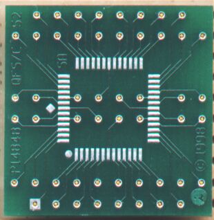
 This image is an example of the sort
of adapter I'm thinking of. Click on it to see it up close. There is a 48
pin PQFP pad set inside a 52 pin PQFP pad set and if you look outside that,
you can see the three rows of pads and holes on each side for the test socket.
The four large holes at the corners are the alignment holes and mounts for
the test socket. The IO pins are arrayed around the edge and there are pads
for Power, Master clear and RTCC next to the header for the ISP in the upper
left.
This image is an example of the sort
of adapter I'm thinking of. Click on it to see it up close. There is a 48
pin PQFP pad set inside a 52 pin PQFP pad set and if you look outside that,
you can see the three rows of pads and holes on each side for the test socket.
The four large holes at the corners are the alignment holes and mounts for
the test socket. The IO pins are arrayed around the edge and there are pads
for Power, Master clear and RTCC next to the header for the ISP in the upper
left.
This layout was done using Express PCBs propritary layout editor before I
knew any better (I'm much more software than hardware) and the layout parameters
became more restrictive when they upgraded the software, makeing this layout
impossible for them to make due to its complexity. Perhaps it's overly complex
for anyone to make!
What's wrong with this design?
-
It's only useable for wirewrap prototyping. The pads on the left and right
sides should probably be rotated down inline with the pads on the top and
bottom. It would make the board a bit larger, but small is no good if only
a few people can use it. Perhaps both arrangements could be provided with
the ability to cut off the ends leaving only the original arrangement when
a smaller board size is required.
-
It was done in a program that is not only unable to define and use library
components, but which is also propritary to only one board house!
-
It doesn't allow enough room for a chrystal or resonator, power regulator,
or reset switch.
-
It's bloody complex!
A commercially available adapter
This is an adapter (pn: 160-8404-07) I purchased from
www.adapters.com some time ago. A great
site if you really, really need quantity one of some wierd adapter that no
one else can get.
What's wrong with this design?
-
Its for wirewrap only.
-
Its designed for the JEDEC MS026 footprint. Ubicom uses the MS022 rather
than the more common MS026. Why? Because the MS022 is exactly half way between
the standard MS026 used in the US and the package foot commonly used by the
Japaneese. Splitting the difference allows the part to fit in assembly part
handlers for either system. But for this adapter, the leads on the chip come
down about half off the solder pads on the top of the adapter requireing
that you manually push all the pins back against the body before soldering.
Not for the faint of heart!
-
The cost is about $65 They do not have an adapter with a socket for prices
less than $250 each min qty 5.
-
Its completely propriatry, and copyrighted.
-
It doesn't allow enough room for a chrystal or resonator, power regulator,
or reset switch.
Contest Requirements
-
Must be GPL or
IPL
-
MUST support the IP2022, but that support can be SMD solder pads or via a
test socket.
-
Must be usable for breadboarding projects in a wide variaty of common prototyping
systems. This requirement is sort of open ended, so I've come up with a point
system for the different possibilities that probably does a better job of
expressing what we might need better than any fixed set of rules.
Point system
-
30 points. Can be made by any standard board
house. Gerber output.
-
20 points. No SMD soldering required. Test socket
layout for SMD parts
-
20 points. Supports onboard crystal or resonator.
-
10 points. Editable in a freeware version of a popular
PCB CAD system.
-
10 points. Editable in a GPL or open source PCB CAD system. Good luck finding
one.
-
10 points. Also supports IP 2000 via SMD pads (the board MUST support the
IP2000, but that support can be SMD solder pads or via a test socket)
-
07 points. Also supports SX28
-
06 points. Also supports SX18
-
05 points. Also supports SX52
-
02 points. Also supports SX48
-
10 points. Usable with a whiteboard for prototyping.
-
07 points. Usable in a 28 or 40 pin DIP socket for prototyping.
-
05 points. Usable for wirewrap prototyping.
-
10 points. Standard 40 pin DIL Headers for ribbon cable connect to another
board or right angle DIL or SIL headers / sockets for direct plug in to mother
board or other boards. See "Maximum interconnect
options from minimum board space"
-
10 points. Supports Dontronics
SIMMStick format
for as many port pins as possible. 16 data lines, 4 serial IO, 6 "address"
lines. So maybe ports A, B and C on the SIMM side with D and E on another
connector. Hint: There is a 30
pin SIL to SIMMStick adapter board available. You just have to have the
SIL in the right order.
-
10 points. Supports RS-232 <-> TTL conversion.
-
10 points. Support Voltage regulator.
-
05 points. Supports onboard reset.
-
10 points. Breadboard area. Hint: Its ok if they have to cut traces to convert
pin header pads into breadboard pads... just as long as its only one or two
easy cuts.
Current efforts
-
I'm working on a new board that may be of some use as a starting point.
Mouser stock numbers 571-41031480 .230 .120 571-41029780 .318 .110
SimmStick Bus Signals. Specifications
updated slightly Feb-2000
Changes Marked In Bold
| PIN # |
Name |
Description |
| 1 |
A1 |
Special IO |
| 2 |
A2 |
Special IO |
| 3 |
A3 |
Special IO or Negative Supply |
| 4 |
PWR |
Unregulated DC (VPP) 7.5 to 18
VDC |
| 5 |
CI/A4 |
Clock In/Special IO Note 1 |
| 6 |
CO/A5 |
Clock Out/Special IO Note 1 |
| 7 |
VDD |
+5V In or Out +/- 5% |
| 8 |
RES |
Reset In or Out. Active Low. |
| 9 |
GND |
Digital Ground |
| 10 |
SCL |
I2C Clock or IO |
| 11 |
SDA |
I2C Data or IO |
| 12 |
SI |
Serial In or IO |
| 13 |
SO |
Serial Out or IO |
| 14 |
IO/A6 |
Special IO |
| 15 |
D0 |
General Purpose IO |
| 16 |
D1 |
General Purpose IO |
| 17 |
D2 |
General Purpose IO |
| 18 |
D3 |
General Purpose IO |
| 19 |
D4 |
General Purpose IO |
| 20 |
D5 |
IO/MOSI or SPI Master Out Slave In Note
2 |
| 21 |
D6 |
IO/MISO or SPI Master In Slave Out Note
2 |
| 22 |
D7 |
IO/SCK or SPI Clock Note 2 |
| 23 |
D8 |
General Purpose IO |
| 24 |
D9 |
General Purpose IO |
| 25 |
D10 |
General Purpose IO |
| 26 |
D11 |
General Purpose IO |
| 27 |
D12 |
General Purpose IO |
| 28 |
D13 |
General Purpose IO |
| 29 |
D14 |
General Purpose IO |
| 30 |
D15 |
General Purpose IO |
Note 1 ***
We feel the most misused, abused, and never used pins are the clock lines.
Should never have come out at all. The guru did make a mistake here. As we
redesign boards, we will remove these tracks, but it could be years now of
course before it filters through. Have added the alternative pin designations
A4 and A5. Scenix Micros use the clock lines for programming, so these may
need to be routed via the "A" lines or perhaps a programming header.
Note 2 ***
For SPI Operation, an additional I/O is required for the Chip Select of each
SPI Device.
Comments:
-
I hope you or a partner can further develope
a breadboard solution for IP 2022.
| file: /Techref/scenix/contest/ip2kadapt.htm, 13KB, , updated: 2013/7/22 18:14, local time: 2024/7/16 00:27,
|
| | ©2024 These pages are served without commercial sponsorship. (No popup ads, etc...).Bandwidth abuse increases hosting cost forcing sponsorship or shutdown. This server aggressively defends against automated copying for any reason including offline viewing, duplication, etc... Please respect this requirement and DO NOT RIP THIS SITE. Questions?
<A HREF="http://piclist.com/techref/scenix/contest/ip2kadapt.htm"> Ubicom IP2022 Prototype Adapter Design Challenge and Contest</A> |
| Did you find what you needed?
|
.
 This image is an example of the sort
of adapter I'm thinking of. Click on it to see it up close. There is a 48
pin PQFP pad set inside a 52 pin PQFP pad set and if you look outside that,
you can see the three rows of pads and holes on each side for the test socket.
The four large holes at the corners are the alignment holes and mounts for
the test socket. The IO pins are arrayed around the edge and there are pads
for Power, Master clear and RTCC next to the header for the ISP in the upper
left.
This image is an example of the sort
of adapter I'm thinking of. Click on it to see it up close. There is a 48
pin PQFP pad set inside a 52 pin PQFP pad set and if you look outside that,
you can see the three rows of pads and holes on each side for the test socket.
The four large holes at the corners are the alignment holes and mounts for
the test socket. The IO pins are arrayed around the edge and there are pads
for Power, Master clear and RTCC next to the header for the ISP in the upper
left.