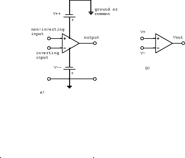
Figure 6.1a shows a complete diagram of an operational
amplifier.
A more common version of the diagram is shown in figure 6.1b,
where missing parts are assumed to exist.
The inverting input means that the output signal will be 180 ![]() out
of phase with the input applied to this terminal.
On the diagram
out
of phase with the input applied to this terminal.
On the diagram ![]() V (DC) and
V (DC) and ![]() V (DC).
V (DC).
![]() is typically, but not necessarily,
is typically, but not necessarily, ![]() V.
The positive and negative voltages are necessary to allow the amplification
of both positive and negative signals without special biasing.
V.
The positive and negative voltages are necessary to allow the amplification
of both positive and negative signals without special biasing.

Figure 6.1: a) Complete diagram of an operational
amplifier and b) common diagram of an operational amplifier.
For a linear amplifier (cf. a differential amplifier) the open-loop gain is
![]()
The open-loop gain can be approximated by the transfer function
![]()
where ![]() is the DC open-loop gain and
is the DC open-loop gain and ![]() is the
transfer function of a passive low-pass filter.
We can write
is the
transfer function of a passive low-pass filter.
We can write
![]()
where ![]() and
and ![]() Hz.
Hz.
Two conditions must be satisfied for linear operation: