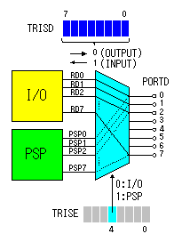
PORTD (Port register D)/TRISD (Port mode set register D) 08h/88h
These registers are the register to be equipped with to 874 and 877. There are 8 ports.
These ports can be used as a parallel slave port in addition to an I/O Port function. A parallel slave port is used when performing 8-bit parallel communication.
The change of the use of a port is specified by PSPMODE bit of a TRISE register. When PSPMODE is "0", PORTD is used as an I/O Port. When PSPMODE is "1", PORTD is used as a parallel slave port (PSP).
When PORTD is used as an I/O Port, the change of an input/output is specified by the TRISD register. Each bit of the TRISD register corresponds to each port of the PORTD register. If the bit of TRISD is set to "0", it will be made an "output port" and "1", it will be made an "input port."
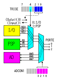
PORTE (Port register E) 09h
These registers are the register to be equipped with to 874 and 877. There are 3 ports.
These ports can be used as the control input of a parallel slave port, and an input of analog-to-digital conversion in addition to an I/O Port function.
The change of a digital port and an analog port is specified by the PCFG bit of ADCON1 register.
Moreover, in the case of a digital port, the change of an I/O Port and a PSP control port is specified by the PSPMODE bit of TRISE register.
When using these ports as an analog input or a PSP control port, input-and-output mode must be set as an input mode.
TRISE (Port mode set register E) 89h
Various kinds of setup about E port is specified by this register.
The value in the parenthesis is in the condition immediately after the turning on.
IBF : Input Buffer Full Status bit ( Read only )
1
:
A word has been received and is waiting to be read by the CPU
0
:
No word has been received
OBF : Output Buffer Full Status bit ( Read only )
1
:
The output buffer still holds a previously written word
0
:
The output buffer has been read
IBOV : Input Buffer Overflow Detect bit (in microprocessor mode)
1
:
A write occurred when a previously input word has not been read (must be cleared in software)
0
:
No overflow occurred
PSPMODE : Parallel Slave Port Mode Select bit
1
:
Parallel slave port mode
0
:
General purpose I/O mode
bit2 : Direction Control bit for pin RE2/CS(inv)/AN7
1
:
Input
0
:
Output
bit1 : Direction Control bit for pin RE1/WR(inv)/AN6
1
:
Input
0
:
Output
bit0 : Direction Control bit for pin RE0/RD(inv)/AN5