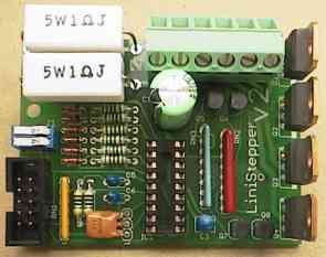
The Linistepper is a well reviewed, open source controller / driver for small to medium sized 5, 6 or 8 wire unipolar (not 4 wire bi-polar) stepper motors featuring ultra smooth old school linear microstepping combined with modern active current regulation from an onboard PIC microcontroller.
Standard step + direction inputs easily connect up to 7 units to a parallel port for for use with standard CNC programs like TurboCNC or Mach 3. A "4 Axis" option is available to provide cable breakout, adjustable mode select, logic power regulation, a relay driver, and a 555 based test circuit.
Supported modes include: Full, Half, High-Torque Half, as well as 6th, 18th and infinite, analog-linear microstepping! A low power hold mode is also available for CNC programs which provide the signal.
Linear drive reduces eddy current losses and heating in the motor typical of chopper type drivers so your motors run cool with no loss of power from the demagnitizing effect of heat! The heat is dissipated at the driver instead through a LARGE heat sink which you must supply (al/alloy with fins and perhaps even a small fan; not steel). Active current regulation combats the traditional slowness of older Linear designs, and the smooth stepping reduces ringing and missed steps giving you a faster top speed from the same old motors.
Professionally made PCBs and Kits are available; priced below the cost of purchasing the individual components, but the circuit, board layout, and firmware are all openly available. Many users have provided modifications, pictures, layouts, etc...
Standard, Full Step |
![]() 3 current levels, 1200 steps, without linear ramping. |
![]() 9 current levels, 3600 steps, with linear ramping! |
Kits
now for sale!
PCB and full kit of parts to build your own!
You supply voltages, heat sink & mounting bracket, unipolar
stepper motor, and step/direction signals.
| $35 each | $90 for 3! USA ONLY | |||
| Postal Shipping (in the USA ONLY) |
1 or 2 units, US shipping |
~or~ | Set of 3, US shipping |
We buy huge quantities: There is just no way anyone can purchase the individual parts to make a few of these kits for less than our kit price! |
| International Shipping (~$15 more) Just about anywhere in the world! |
The 3 unit price is not available by Credit card payment outside the US due to customs fraud and lack of seller protection from PayPal. Please contact James Newton for pre-payment options. | |||
Also available: Set of 3 Printed Circuit Boards for $35.00. These are VERY well made boards and are certainly worth the price IF you have a well stocked scrap box to populate them. However, you will find our kit price of $75 for 3 complete kits is MUCH LESS than the cost of parts and PCBs, AND the PIC comes already programmed! |
USA only! |
or | |
Can't be made for less! |
|||
![]() |
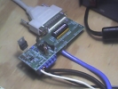
Connect to your PC or stand alone:
|
BTW to all those newbies out there Linisteppers impressed me as a newbie but then they were starting to show their weakness - they were sloooow. At least I thought it's due to linisteppers. Well, I can report that with 24v and laserjet steppers these things are SCREAMING!!! I'm running them nicely at 20revs/sec (albeit 1 minute at a time, until I've sorted out my cooling problems) with my very rough machine that hasn't been executed too precisely or adjusted properly. Before at 12v the motors would stall at the slightest misalignment and 6revs/sec was all I could get out of them reliably. Once all that is ironed-out I'm thinking 30revs/sec (1.75mm lead) would be attainable....
[The Linisteppers] only deficiency, it seems, is the transistor heat. I have a chopper here and a linistepper and they both run at 24v. Linistepper "sounds" sweeter and it seems it runs faster as well before stalling. This is strange as I always thought a chopper would go faster and stall higher up in the rev range.
...
I don't know what I like better, burning my finger on the driver board or burning my finger on the motor. Which do you prefer? P.S. it seems that once I switched to a chopper driver all that heat that used to be on linisteppers just transferred to motors themselves!
...
[ed, at this point, we find out that there was NO heatsink on the linisteppers power transisters]
Since I burned my fingers on a motor that was driven by a chopper (and that motor was actually HOTTER than linisteppers driving other motors) I have decided to stick to linisteppers. It's easier to worry about heat in one place than 3 separate locations. Went down to my local PC shop and they'll have some 2nd hand pentium II coolers with fan in by monday....
Ok, I have re-assembled one of my linis, applied thermal paste, applied isolators to each, mounted the brackets and laid a 12v computer fan on the brackets blowing DOWN through the brackets and onto the lini. The lini transistors are now as cool as ice.
Suggestion: Make a note of the changed capacitor values in the printed instructions.
Request 1: Make a bipolar controller next! (3 or 4 wire) Please!
Request 2: Offer or specify "upgrade kit" with *specific* directions of what to change, for higher amp motors (for people like me who don't know what they're doing).
Compliment: Very professional looking. I'm sure I'll be pleased with the performance, when I finally finish one.
James
Newton replies: I'll do that.
Bipolar controllers are inherently more expensive (4 times the power transistors)
and less attractive in a hobby market.
People who don't know what they are doing should learn but I've been thinking
I should try to write some sort of "expert system" to help that along.
Thanks and best of luck.+
Hello,Received your kit today (saturdaymorning 9 Nov.) Thank you Verry Much!
Looks verry Proffesional made!
I do not have the time at the moment to build an test it and i don't have the alluminium heatsink at homei have placed the components on the board all fits well i think except C3 holes are 2,54mm wide and should be 5,08mm wide {Ed: Component changes caused that... The leads can be bent to fit for now}
also it would be better to place picture off the caps position on your kitassemble page people look better than they read or place caps + - on the silkscreen off the board {Ed: Done!}
maybe you could give some more info/pictures about the resistors and colors on your kit assemble page maybe a picture with lines outside the picture with describing text off resistors (colors) {Ed: Done!}
think this could help other people making mistakes placing components
verry nice kit
question where do you get this good quality pcb board made?? {Ed: GRIN!}
greetings luberth
netherlands
Roman Black - Aug 2002 This design is Hippyware Basically this is just a board I designed for my own use, that ended up as a kit. It is easy to build and is well suited for motors around 1A/phase. It can be re-configured to do larger motors with some resistor changes and a large enough heatsink. I like things rugged and simple, which it is. Yes it is linear and makes heat (like a big audio amp does). It has some unconventional features like hardware AND software microstepping, and current ramping to give almost "stepless" operation at the tuned speed. And it will suit industrial apps with continuous use etc, no "toy" stepper chips in this design. 3600 steps per revolution with a 200 step motor! My original design goal was to make a board that could be used for many different projects. If you choose you can modify this design to suit different tasks. Circuit operation is simple and easy to understand and test and PIC .asm source code is supplied. Full indexing, motion control etc on one circuit board is possible if you wish to reprogram it.Using the board! Tips for using the board and keeping it cool. How to tune the board for currents other than 1A. Tuning the board for different sized motors requires changing the 2 sense resistors, this page also covers software mods. More info here.Almost stepless operation... The board can be "tuned" for a specific speed band, and steps are smoother through ALL rev ranges with the built in step ramping. How the board works (long). Instructions! As this is a kit of parts, here is a page on: How to build it High-Torque half-stepping! I use a little known form of half- stepping as one of the main modes. More about the special half-step system: High-Torque half stepping Circuit Diagram click here. PCB (Board) Layout click here. PIC Software click here to READ it. PIC Software click here to DOWNLOAD it as a ZIP file.
Picture of the linistepper driving a 5v 1A motor.
The other circuit board is a 555 timer and some dip switches,
that clocks the STEP input and can switch the DIRECTION and
LOW POWER inputs and change the stepping mode between 200, 400,
1200, 3600 steps/rev. The heatsink shown looks large as my camera
has a slight "fish-eye" lens.
-end
Stepper Controller at PICList.com
Stepper controller information presented at PICList.com.
Stepper controller sources by clicking above.
Find stepper controller on PICList.com.
PICList.com - Serial Level Conversion, Stepper Motor Control, and IIC Control.
PICList.com offers custom engineering services such as hardware or PC software
development for our existing products.
PICList.com Inc. provides custom engineering services to customers worldwide.
To provide us with a description of your project, please contact us by email
at: info@piclist.com.
Related terms are
serial peripheral interface specification,
understanding motor control diagrams,
build serial port interface, and
motor control.
Should for any reason you change your mind about our products, you may ship
them back for a refund.
We also ship worldwide.
Embedded microcontroller design.
PICList -web site hosting, custom, small business, search, engine, optimization,
corporate, animation.
Stepper controller sources at PICList.com.
We specialize in combining PC software with external hardware for data
acquisition and process control.
Web design firm producing New Media Promotion, Web design, Portfolio design,
Presentations and Advertising.
Stepper controller related phrases are on PICList.com.
PICList -San Diego web design, web design, webdesign, Los Angeles, DMD studio,
web site design, affordable, flash design.
We specialize in combining PC software with external hardware for data
acquisition and process control.
Related terms include
understanding motor control diagrams,
cd-rw digital audio format data,
serial peripheral interface specification,
build serial port interface, and
diagrams 3v motor control.
PICList.com is presently preparing marketing and technical information on
newly developed products.
PICList.com Inc. provides custom engineering services to customers worldwide.
Look for stepper controller on PICList.com.
Terms that are related are
understanding motor control diagrams,
motor control,
cd-rw digital audio format data,
build serial port interface, and
serial peripheral interface specification.
PICList.com Inc. provides custom engineering services to customers worldwide.
stepper controller is related to PICList.com.
We specialize in combining PC software with external hardware for data
acquisition and process control.
We also ship worldwide.
Digital and low frequency analogic circuit design. -
Embedded microcontroller design.
Other related phrases are
motor control,
cd-rw digital audio format data,
serial peripheral interface specification,
understanding motor control diagrams, and
build serial port interface.
Should for any reason you change your mind about our products, you may ship
them back for a refund.
PICList.com is presently preparing marketing and technical information on
newly developed products.
PICList.com -web site hosting, custom, small business, search, engine,
optimization, corporate, animation.
We specialize in combining PC software with external hardware for data
acquisition and process control.
Feedback:
How to blow up the Linistep (or avoid doing so) Hint: It isn't easy to destroy and even then, repair is cheap...
See also:
Questions:
+
Hello, can the linistepper be upgraded by the use of FETs of higher power? I'm looking at steppers with 4.6v 2.5a per phase, and 300inlb.
Thanks for your time.
James Newton replies: Certainly, however the engineering of that is left "as an excersize for the student." There is some information available at http://www.piclist.com/techref/io/stepper/linistep/lini_tun.htm+
Bought it, built it, and then realized that my bi-polar motors (painstakingly chosen) will not work on it. The Linistepper seems perfect for my prototype if only it came in a bi-polar version! I need to buy it in a heartbeat.
James Newton replies: Sorry about that! The page above does say that this is not for bipolar motors, but perhaps it's good to say that again here.+
Hi,
From the schemetic diagram, I found out there are resistors connected in series: R18 with R19, R20 with R21, etc. In actual board layout, I saw only one resistor being soldered, ie R18/R19 = 150 ohms. Could you please advice? I am confused. Is 150 ohms equal to two resistors in series? Or can I substitute the pair resistors with one resistor only?
Thank you.
Rgds,
Chris
James Newton replies: You can use all or only one resistor in those places to adjust the resistance and fine tune the operation of the controller. See the page on tuning the linistepper for details.+
http://www.call-mac-then-pack.com/hobby.htm Someone must have already revised these boards to put out 2.3 amp. I can solder and thats about it. Trying to get my motors to work like they should, 2.3 volt & 2.3 amp unipolar applied motion products. If I knew what to get I could install it on my boards. Can you please help me. Bought the boards from you and more sales to me are fourthcomming.
James Newton replies: Please read this web page: "How to tune it for special needs!" especially the section under the heading "Changing Current." It really isn't terribly complex. Changing the sense resistors to one half ohm (or soldering another 1 ohm resistor in parallel) will give you 2 amps. For 2.3 amps, for each coil, you need a 1 ohm (already supplied as R1 or R2), plus another 1 ohm (R3 / R5), plus a 30 ohm resistor (R4 / R6) all soldered in parallel. Make sure your heat sink is a good one!+
Hi,
I posted before, but I can't find were it is. I was looking in the Mouser catalog and found a PNP power transistor that might possibly be used to get more current out to hungryer motors. The part number is 511-MJ2955 and is rated at 15 Amps at 70 Volts. It is in a TO-3 case which will require special mounting to the heat sink with remote wires to prevent smoking the foil traces. Would this transistor work O.K.? Jack
James Newton replies: It looks like it is worth a try...+
The parts list and the circuit diagram/board overlay disagree on the value of C4 and C5 - 2.2pF vs 4.7pF
The boards arrived in Australia really quickly! Very impressed thanks :)
James Newton replies: Either value works just fine; the exact capacitance is not that critical.+
Hello,
I have built two Linistepper module to replace GS-D200S cards who activated a home built PCB engraving machine.
I can whitness that movments now are very smooth and quiet, huge difference with previous drivers. I think that Z axis will be fitted soon with a Linistepper !
I would like to modify resolution to get 1000 or 2000 steps/revolution, do you think that it is possible ?
I have not a great Pic experience but I'm looking your software 'step-by-step' to understand your work and try to adapt it to my use.
Thank you very much to provide me with some answer, and congratulation for this design.
Best Regards,
Michel
James Newton replies: I'm very glad to hear that the unit worked well for you.
The linistepper already offers 3600 steps per revolution simply by setting the jumpers on the board, so I am confused by your question.
It is possible to modify the code (this is an open source product) for any number of new features, but honestly, it is very difficult. The PIC code for the Linistepper was written by a true genius (NOT ME! The author is Roman Black) in PIC programming and it packs a lot of features in a very small amount of code. Improving on that will be difficult without experience in PIC programming. For someone with PIC experience, it shouldn't be terribly difficult give the existing code as a start.
Excuse me if this question seems a little simple, but I'm not well versed in matters electronic. Can someone tell me exactly which parrallel port pins connect to which pins on the stepper controller? Much obliged.
James Newton replies: Actually you can connect any of the "D" or Data lines to any of the inputs on the Linistepper. Some ideas are listed at the FAQ page and there is a page that shows exactly what pins are available on the parallel port connectors.+
Hi,
Do you have any parallel port interface or do you know where I can find one.
Just checking before I buy something my software can only drive parallel port interfaces.
Leffe
James Newton replies: The linistepper can be driven by any standard TTL signal, including those from a standard PC parallel port.+
Questions:
I'm dumb or whatever...?! At least, I didn't deal with PIC's in whole my life... :-) Anywhere, I'm trying to find out which PIC is appropriate for the *.hex file you gave to us!? IS that 16F84, 16F84A, 16F628 or 16F628A and do we have to use only 20MHz MCU's? Please be patient and answer these question for dummy!
greetings
James Newton replies: I'm not sure what .hex file you are referring to. The source code is available for p16f84A or p16f628 at http://www.piclist.com/techref/io/stepper/linistep/lini_asm.txt. You need MPASM from Microchip to compile it. The clock does not have to be 20MHz, but it may miss very fast step pulses with a clock that is too slow. tratincica-spinter- replies: I reffered to http://www.piclist.com/techref/io/stepper/linistep/lini_01.hex hex file. It's already compiled but I do not know what PIC type I have to use with this compiled file. I have no MPASM neither do I know deal with it. I've just planned to use your hex file... sorry for bad english and thank you for replying. James Newton replies: Actually I'd forgotten about that one.. That file is for the 628. tratincica-spinter- replies: . Thank you for fast and accurate info. I'll post here pictures of my hardware and feedback infos when complete linistep (3x). Greetings from Serbia+
I purchased a stepper motor clock drive that I am planning on driving with your linistepper/ 555 pulse generator. I have no idea what the manufacturer had previously as a driver but I did notice that each common has a precision 3 ohm resistor attached to it (the windings resistance is also 3 ohms - doubling the motor's resistance): is this to draw more voltage and would this increase smoothness or accuracy (the desired features in a clock drive)? I am assuming that these resistors would NOT be useful with the linistepper?
James Newton replies: Those resistors are left over from an old style linear driver. They are replaced by an active circuit in the Linistepper that uses current sensing and transistors to increase the performance of the motor. Remove them before connecting the Linistepper and all should be well.+
Dear Sir, I was wondering why not using a Mosfet instead of Darlington JBT, I mean... Mosfet have a much faster on/off speed an d can produce higher micro steps during low speed and give full power during right speed right?
James Newton replies: MOSFETs aren't generally linear.+
Hi (hope this is the correct place to ask) i was wondering if this is what i need for my project. Iam building a 4 filter slider for a camera which needs to move to each filter then return to the begining after each photo is taken. I actually know next to nothing about motor control at the moment, is this possible with the kit? i can solder and follow instructions etc i just am unsure if this will do what i need. Thanks for your time. Ryan
James Newton replies: This would work to drive the stepper motor, but you would still have to find some logic to generate step and direction pulses to active this controller. I'm not sure what to say about that, but the 555 kit might help if you could find a way to switch the direction signal and stop the pulses between pictures.+
Is it necessary to use the pic16f84 20Mhz instead off the 4Mhz version ? Is it necessary to use the 16Mhz crystal , because in the circuit diagram it's a little complicated .
Greetings Wendy
James Newton replies: You must always use a PIC that is rated at or above the speed of the crystal.+
/techref/io/stepper/linistep/2b1records.com The linisteper works great. I am very pleased - question though. I have another project that needs 5amp's how would you requmend steping up the output. I guess the Heat sinks would be huge - I could use fans, I could use a dalenton high current maybe TIP41C?. What do you suggest - Boots-2b1
James Newton replies: All of the above... And 5 amps is probably do-able with care. Or just put out the money and go to a high end chopper.+
Comments:
Hi, I am thinking of building a table of 2 axes but I am zero in electronics. If I have an engine of 2 phases, (0.8 A / phase and 6Vdc) or higher, which should be the criteria for selection of components (C2, 4 C3 C5, 6 D1-6 and the general C1) given the voltage that passes through them. It must be equal to the voltage of feeding the engine or higher. (I know only that in C1 should use a V above) Already now, the site is 100%. The best kind of with open source.
Thank you, I await a response
________________________________________________LuÃs F.
James Newton replies: All the component values for the Linistepper are listed on the schematic... For tuning it for different current levels, see http://www.piclist.com/techref/io/stepper/linistep/lini_tun.htm. That page even has a little javascript to calculate the values of the sense resistors for you.+
Thank you very much for sharing this nice design!
To make it even more useful, it could provide a way to hook end-switches to it.
Maybe change the input scheme:
Inputs RA3 and RA4 are used to connect end-switches.
If either of both goes high, further steps in the current direction are ignored.
If RA3 and RA4 both get high, "programming mode" is enabled, and RA2 selects
power mode, RA1 resp. RA0 serve as mode bits.
I'm not used to PIC programming, but maybe somebody is willing to implement this...
| file: /techref/io/stepper/linistep/index.htm, 51KB, , updated: 2008/7/8 19:43, local time: 2008/8/29 12:47,
owner: RB-ezy-Q33,
38.103.63.61:LOG IN
|
| ©2008 These pages are served without commercial sponsorship. (No popup ads, etc...).Bandwidth abuse increases hosting cost forcing sponsorship or shutdown. This server aggressively defends against automated copying for any reason including offline viewing, duplication, etc... Please respect this requirement and DO NOT RIP THIS SITE. Questions? Please DO link to this page! Digg it! <A HREF="http://piclist.com/techref/io/stepper/linistep/index.htm"> Linear Stepper Motor Controller</A> |
| Did you find what you needed? |
|
|
.